Wound Rotor Induction Motor with Subsynchronous Converter Cascade in the Rotor Circuit:
The following points favour the application of a slip ring motor having static slip energy recovery scheme in the Subsynchronous Converter Cascade circuit, to drive a centrifugal pump (Fig. 7.10).
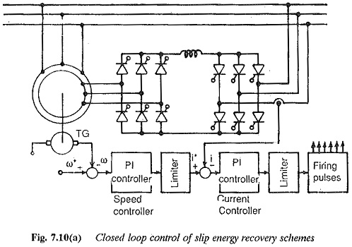
1.The delivery rate control of the pump is accomplished by speed control of the pump. The speed control of the motor is done by recovering the slip energy to the mains. The system has no slip losses, i.e., losses occurring due to drop in speed, Therefore the power requirement of the drive is to drive the load, plus Wound Rotor Induction Motor with Subsynchronous Converter and motor losses only. Based on the power consumption the system is preferred as it is very efficient.
2.A very smooth stepless control is possible, to avoid surges in the hydraulic system due to switching the pump sets on and off
3.Design capacity of static converter; the advantage of Wound Rotor Induction Motor with Subsynchronous Converter cascade in the rotor of an induction motor over the stator fed converter drives is that the static converter cascade need not be rated for full rating of the motor. The rating of the converter depends upon the range of speed control required below synchronous speed. As the speed range is limited to 30-50% the converter cascade also needs to be rated for 30-50% of the full However the converter should be so designed that it is capable of conducting the highest possible current at high speed and withstanding the highest possible voltage at the lowest speed. To accomplish this the actual design rating of the Wound Rotor Induction Motor with Subsynchronous Converter is slightly greater than the slip power. As the highest current and highest voltage do not occur simultaneously, the design rating of the Wound Rotor Induction Motor with Subsynchronous Converter can be reduced by switchable cascades.
4.Starting: Smooth starting of the motor is possible. The torque can be regulated by means of link current of cascade. The starting current peaks are not there.
5.Operating safety and flexibility: The system has increased operating safety and provides flexible availability of the installation. In case of cascade converter failure and in any other emergency condition, it is possible to run the motor having speed control by means of varying the rotor resistance employed for starting. However the rotor resistance must have been designed to serve both the jobs. This possibility is not there with other systems. There is another flexibility of operation in using a Wound Rotor Induction Motor with Subsynchronous Converter. A given unit can be used with several induction motors and hence fewer converter cascades than pumps may be used. This is feasible if all pumps do not require speed control at the same time. Only that pump which requires speed control is used with the cascade and the pump which does not require speed control is used with normal induction motor. The pump to be regulated can be chosen at will and consequently the installation has a very highly flexible control.
6.The system can be developed for all power ranges and speeds of centrifugal pumps. The highest speed that is available is 1800 rpm and in exceptional cases this can be extended to 3600 rpm. Subsynchronous converter cascade is superior to converter fed dc motors with respect to this criterion. It is however inferior to converter fed synchronous motors which are available for speeds up to 6000 rpm.
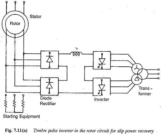
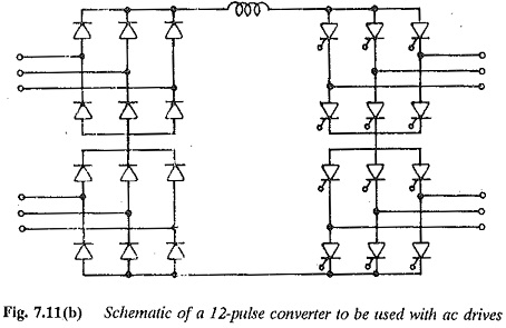
7.To improve the performance, the following modifications are made in the development of the converter. A 12 pulse converter (Fig. 7.11) may be used to decrease the amplitude of pulsating torques and harmonic losses in the motor. The 12 pulse inverter presents only higher order harmonics and the line voltage distortion will be small. The pulsating torques are affected by the number of pulses of the rectifier. The 12 pulse arrangement of the inverter decreases the torque pulsation by decreasing the stator current and voltage distortion. 12 pulse inverters are required if the short circuit rating of the mains is lower than that of the motor. It is also required if the line is such that the harmonics of the inverter are capable of causing distortion
8.The main disadvantage of converter cascades is poor power factor due to phase control of the line side inverter. Methods have been developed to improve the power factor. One of these methods is the sequential control of the inverter on the line side. Sequential operation improves the power factor by requiring reduced reactive power.
Converter Fed Synchronous Motor Drive for Centrifugal Pumps
Converter fed synchronous motor satisfies all the above discussed criteria and has application to driving centrifugal pumps. Compared to the slip ring rotor with converter cascade this has advantages of:
- higher speed of operation up to 6000 rpm
- the simple converter due to machine commutation (with commutation assistance only at low speeds)
- the line power factor is better than converter cascade
- The features of soft starting and possibility of achieving a gearless drive both at very low and high speeds.