Basic Elements of Electric Drive:
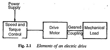
Basic Elements of Electric Drive- Before discussion makes clear that an electric drive system basically consists of a mechanical load to which the required mechanical motion is imparted through a transmission drive usually equipped with gears or pulleys. Gearless transmission is possible sometimes, in which case there exists a direct coupling between the motor and load. The system also comprises certain controls for the motor for precise adjustment of the speed-torque curve as demanded by the mechanical load. The elements of a typical variable speed electric drive are depicted in Fig. 2.1.
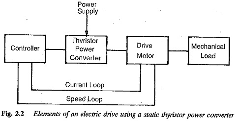
The function of the control equipment is to set the desired speed or torque precisely. Until the advent of thyristors and associated power converters the speed control of motors had been achieved by means of contactors and relays, which include or cut off the resistors. The development of power converters has made the control of motors quite straightforward. With this help the speed of ac motors is also smoothly variable. The elements of a drive system when converters are employed are shown in Fig. 2.2.
Among these elements, the mechanical load and its characteristics are normally specified by means of its load diagram and torque-speed curve. A motor and its controls have to be selected to suit the iven power supply and drive the load. We now discuss various types of load and their characteristics in detail.
Mechanical system
The mechanical system is coupled to the motor by means of a transmitting device. The motor has to develop a torque as required by the mechanical work to be carried out to drive the load, and the mechanical losses occurring in the system. A mechanical system is specified by a speed-torque curve. The motor while driving this mechanical load must provide enough torque to drive the load against losses like friction and to accelerate the load toque to the desired speed. Hence the load torque required by the load at the shaft has the following components.
- Torque component to overcome friction and windage which accompanies mechanical motion.
- Torque required to accelerate the load to the desired speed.
- Torque required to do the prescribed mechanical work, i.e. to run to the load at the desired speed.
The load torque seen by the motor at the shaft
![]()
Mechanical motion is accompanied by frictional forces between the surfaces undergoing relative motion. Frictional forces of both the load and the transmission equipment have to be considered. Also, the electromagnetic torque developed by the motor has to provide for its own friction and windage before appearing at the shaft to drive the load. The torque to overcome the friction should be delivered by the motor to keep the mechanism in motion when the system is on no load.
The friction existing in a mechanical system may be classified as follows:
1.Viscous friction: In this type of friction the torque required is directly proportional to the speed of rotation ,
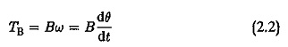
where B is a constant of proportionality. This is depicted in Fig. 2.3. It occurs in well lubricated bearings and the laminar flow of lubricating liquids.
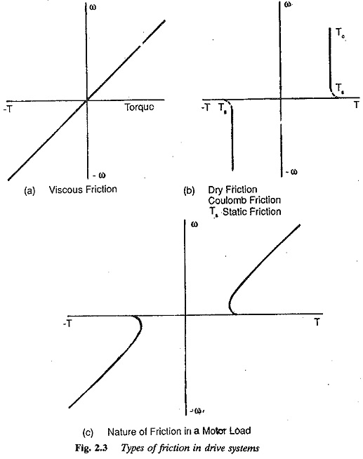
2.Coulomb friction: The torque required is independent of speed in this type of friction. It acts as a load torque in either direction and is also called dry friction. Viscous friction changes to coulomb friction at very low speeds.
3.Static friction or stiction: Occurs due to the sticking nature of the surfaces. This is generally very small and can be neglected.
Windage torque
The torque required by the load when the air surrounding the rotating parts moves. It is normally proportional to the square of the speed. However, at normal speeds of operation it may be considered equivalent to viscous friction and the value of B may be taken to contain both friction and windage.
The working mechanism must be accelerated and brought to the desired speed. The motor should provide a torque at the shaft capable of accelerating the rotating parts against, their inertia. Inertia, as seen by the motor shaft, includes the inertia of the mechanism as well as of transmission. The inertia of the rotating parts of the motor is taken care of by the internal torque developed by the motor before it appears as a shaft torque. Taking J as the inertia of the mechanical system,
![]()
A torque component may exist sometimes due to the torsional elasticity of the shaft. This has to be considered under transient conditions and is given by![]()
i.e. it is proportional to the torsion angle of coupling. The constant of proportionality K is called the stiffness of coupling. Normally the shafts are perfectly stiff and this component does not exist. However, if it does, it represents a store of potential energy where Ta represents kinetic energy. Under ideal conditions without friction, there exist oscillations leading to the shaft breaking.
The useful working torque required to do the mechanical job is a function of speed
![]()
Therefore the total torque required at the shaft
![]()
Considering the acceleration of the motor against its inertia and friction, the electromagnetic torque developed is
![]()
Let us now study the various types of load torques that occur in industrial practice.
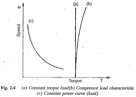
The load torque may be constant at all speeds, as shown in Fig. 2.4 by curve (a). This type of torque is represented by a compressor load and the speed-torque curve is as shown by the curve (b). This drive is unidirectional. Another type of load has its torque proportional to the square of the speed,as shown in Fig. 2.5.
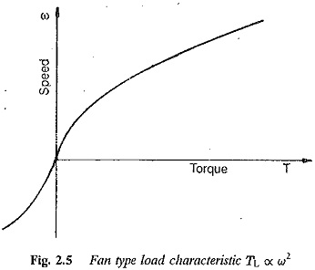
This speed-torque curve is found with pump or fan type loads.
![]()
The power developed at the motor shaft
![]()
This load is also unidirectional. It is required to run at constant speeds for a longer period of time or at several speed settings or over a range of speeds.
Another type of mechanical load requires constant power at all speeds
![]()
P constant at all w. The torque-speed characteristic of such a load is a rectangular hyperbola. ‘This load is found with steel rolling mills, papers mills, etc. It occurs in transportation also. The torque-speed curve is shown in Fig. 2.4 (c). With certain types of loads, like winch drives, a constant torque is required when the mechanism is under standstill conditions. The direction of rotation may need to be reversed. These occur in ships when it is required to hold the ship in a particular location or to warp it through a lock gate.
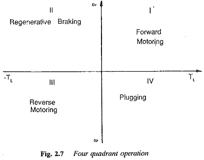
From the above types of loads one can easily see that some operate only in one direction with no reversal of speed. In the speed-torque plane these are represented in the first quadrant. The forward driving of the mechanism corresponds to an operation in the first quadrant where motor draws electrical power to drive the mechanical load coupled to it.
The mechanical load sometimes requires braking to bring it to rest quickly. During braking, which torque is achieved either by electrical or mechanical method is applied in the negative direction. Electrical methods are dynamic braking, eddy current braking, regenerative braking and plugging. In dynamic braking, the machine driving the load acts as a generator and the kinetic energy of the rotating parts is converted to electrical energy and dissipated in the resistances. In eddy current braking this energy is dissipated in eddy current losses or resistance losses in a specially constructed machine. The energy of the rotating masses, instead of being dissipated, is returned to the mains in regenerative braking. Another kind of electrical braking is called plugging or reverse current braking. A motor acts as an electric brake. The motor develops a negative torque whose nature is to produce a torque which would oppose the direction of rotation already existing. In mechanical braking, the energy of the rotating parts of the system is dissipated as heat due to friction in the mechanical brake coupled to the system.
Operation in the second quadrant represents braking, because in this part of the torque-speed plane the direction of rotation is positive and the torque is negative. The machine operates as a generator developing a counter torque which opposes motion. The K.E. of the rotating parts is available as electrical energy which may be pumped to the mains or in dynamic braking, dissipated in some resistances.
In the third quadrant which corresponds to motor action in the reverse direction both speed and torque have negative values, while power is positive. Operation is similar to that in the first quadrant, with direction of rotation reversed.
In the fourth quadrant the torque and speed have opposite signs —positive and negative respectively. The operation can be examined in either of two ways. The motion in this quadrant may be under the action of load itself. The motor tends to attain dangerously high speeds. The motor must develop a torque which opposes the acceleration due to load. The motor acts as a brake. This quadrant corresponds to braking in reverse motoring. The transition to this may be also from the third quadrant if there is a tendency of the motor to accelerate in the reverse direction. The generator torque developed arrests the acceleration. This situation occurs when a hoist is lowering the load. These operations in all four quadrants are depicted in Fig. 2.7.
Compressor, pump and fan type loads require operation in the first quadrant only, since their operation is unidirectional. They are one quadrant drive systems.
Transportation drives require operation in both directions. The method of braking depends upon the conditions of availability of power supply. Braking may be electrical or mechanical. If regeneration is necessary, operation in all four quadrants may be required. If not, operation is restricted to quadrants 1 and 3. Dynamic braking or mechanical braking may be employed.
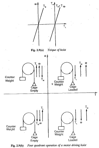
In hoiSt drives a four quadrant operation invariably occurs. The speed-torque curve is depicted in Fig. 2.8. The operations are shown in Fig. 2.9. The first quadrant represents the operation of the hoist while going up. The load in the cage has to be moved against gravity and a motoring torque occurs. In the second quadrant the cage movement remains upwards. The load torque is not there because of the absence of load. Under the action of the counter weight, very high speeds may result, causing regeneration. For operation in this quadrant, and as a safety arrangement, a mechanical brake is provided, which brakes the mechanism in case of power failure. It also helps to hold the suspended load stationary at any point and prevents excessive acceleration. Dynamic braking may also be applied for quick stopping.
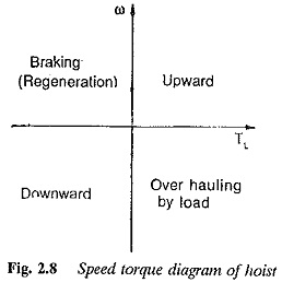
In the third quadrant the direction of rotating reverses; the load is lowered by the hoist. In case of acceleration of the load under gravity, there is a slight transition to the fourth quadrant, wherein regenerative braking or dynamic braking may occur, limiting the speed of motion.
The load moves downwards in the fourth quadrant. It overhauls the motor and may cause regeneration. Under gravity the acceleration might result in dangerous speeds. ‘Therefore the motor is made to act as a brake and develop a torque to run the motor in the positive direction, opposite to the load.
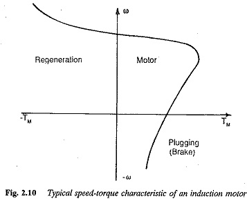
Typical speed-torques of an induction motor and dc motor are shown in Fig. 2.10. Under steady conditions of the drive the operation is restricted to 1, 3, and 4 quadrants. Regenerative braking takes place in the second quadrant under transient conditions. Plugging may take place in the second quadrant for motoring operation in the third quadrant.
In some types of loads the load torque depends on the position of the load during motion. For example, a train moving up a gradient will have different torque compared to one moving down it, or on a level track or along a curve. Another example of such loads is the hoisting mechanisms where the weight of the rope affects the Load torque, depending upon the position of the load.
It may act as a load, requiring power from the drive motor, or as an effort moving the load in the required direction. This might cause a jerky operation of the hoist and needs to be compensated by tail ropes.
While selecting a motor for driving a load, if is necessary to consider the variation of load torque with both speed and time. The torque-speed curve normally decides the type of motor, whereas the variation of load with time decides the rating of the motor. Loads that occur in industrial practice can be classified depending upon their variation with time, which is specified by the load diagram. A load whose torque is independent of speed may be a continuous load or appearing intermittently in a periodic manner. A fan type load where T α N2 may also be continuous or occurring intermittently. Hence loads may also be classified depending upon the duty they have to perform.
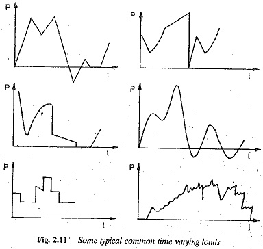
The classification, according to variation with time, is as follows:
- Continuous constant loads: These loads occur for a long time under the same conditions, e.g. fan type loads.
- Continuous variable type loads: The load is variable over a period of time, but occurs repetitively for a longer duration. It occurs in metal cutting lathes, conveyors, etc.
- Pulsating loads: Certain types of loads exhibit a torque behaviour which can be thought of as a constant torque superimposed by They are present with reciprocating pumps and all loads having crank-shafts.
- Impact loads: Peak loads occur at regular intervals of time, t.g. in rolling mills, forging hammers, etc. Motors driving these loads are equipped with flywheels for load equalisation.
- Short time intermittent loads: The load appears periodically in identical duty cycles, each consisting of a period of application of load and one of rest. Cranes and hoisting mechanisms are examples of this type of loading.
- Short time loads: A constant load appears on the drive for a short time and the system rests for the remainder. Battery charging and household equipment offer such loads.
These types of loads are depicted in Fig. 2.11.