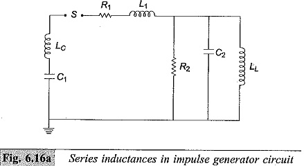
Series Inductance in Impulse Generator Circuit:
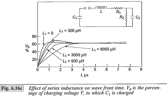
Often Series Inductance in Impulse Generator Circuit are required to test equipment with large inductance, such as power transformers and reactors. Usually, generating the impulse voltage wave of proper time-to-front and obtaining a good voltage efficiency are easy, but obtaining the required time-to-tail as per the standards will be very difficult.
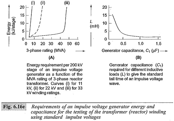
The equivalent circuit for medium and low inductive loads will be as shown in Fig. 6.16d. For the calculation of time-to-tail the circuit can still be approximated as a series C-R-L circuit. As the value R/(√L/C) decreases, the overshoot and the swing of the wave to the opposite polarity increases thereby deviating from the standard wave shape. Therefore, it is necessary to keep the value of the effective resistance R in the circuit large. One method of doing this is to connect a large resistance, R2 in parallel with the test object or to connect the untested winding of the transformer (load) with a suitable resistance. Another method that can be used is to increase the generator capacitance with which the time-to-tail also increases, but without alterating the time-to-front and the overshoot. Figure 6.16(d) gives the circuit arrangement for inductive loads and 6.16(e) gives the requirement of energy and capacitance of the impulse voltage generator. Figure B of 6.16(e) gives the generator capacitance required to give the time-to-tail values in the range of 40 to 60 μs at different inductive loads.
Waveshape Control
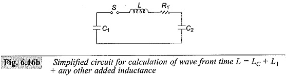
Generally, for a given Series Inductance in Impulse Generator Circuit of Fig. 6. 15b or c the generator capacitance C1 and load capacitance C2 will be fixed depending on the design of the generator and the test object. Hence, the desired waveshape is obtained by controlling R1 and R2. The following approximate analysis is used to calculate the wave front and wave tail times.
Where
Lc —Inductance of the generator capacitance C1 and lead capacitances
L1— Inductance of the series resistance and the circuit loop inductance
LL — Test object inductance
The resistance R2 will be large. Hence, the simplified circuit shown in Fig. 6.16b is used for wave front time calculation. Taking the circuit inductance to be negligible during charging, C1 charges the load capacitance C2 through R1.
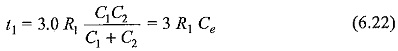
Then the time taken for charging is approximately three times the time constant of the circuit and is given by
where,
If R1 is given in ohms and Ce in microfarads, t1 is obtained in microseconds.
For discharging or tail time, the capacitances C1 and C2 may be considered to be in parallel and discharging occurs through R1 and R2. Hence, the time for 50% discharge is approximately given by
![]()
These formulae for t1 and t2 hold good for the equivalent circuits shown in Figs 6.15b and 6.15c. For the circuit given in Fig. 6.15d, R is to be taken as 2R1. With the approximate formulae, the wave front and wave tail times can be estimated to within ± 20% for the standard impulse waves.