Field Oriented Control of Three Phase Induction Motor:
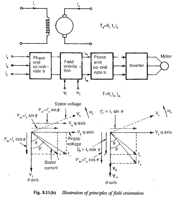
The stator current of an induction motor has the functions of producing the required air gap flux (magnetisation) as well as developing the required torque to drive the load. An Field Oriented Control of Three Phase Induction Motor motor will have its operation similar to that of a dc motor if the stator current components (viz., flux producing and torque producing) can be separately controlled. This kind of control is possible in a separately excited dc motor where the torque and flux can be separately and independently controlled by varying the armature current and field current respectively. An inherent decoupling would exist between them, but for the effects of armature reaction. These effects can be eliminated by armature compensation. A perfect decoupling can be achieved in a compensated separately excited dc motor. This versatile control imparts a very good dynamic behaviour to a dc motor. Thus a high performance drive using an Field Oriented Control of Three Phase Induction Motor is achieved by attempting a decoupling of the stator current components. This principle is called field orientation control or vector control. This control improves the dynamic behaviour and a drive of very good performance can be obtained even at low speeds. The two components of the current are identified and they are oriented properly in orthogonal ordinates with respect to flux vector.
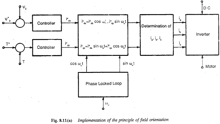
The current components can be oriented with respect to any of the three fluxes, viz., stator flux, air gap flux or rotor flux. The analysis shows that the dynamic performance of the drive is not up to the desired level if the orientation is carried out with respect to the stator or air gap flux. This poor dynamic behaviour stems from the delay of the torque in following the slip. A natural and efficient decoupling is possible if the orientation is carried out with respect to the rotor flux, This leads to a high performance torque control of the drive with a Very fast response. The implementation of the principle of field orientation is illustrated in Fig. 8.11.
 When the principle of field orientation was suggested, it did not receive the attention of the industry and was not very popular because of complicated hardware. With the developments in digital components and microprocessors by way of LSI, and miniaturisation of the components, this high performance control of Field Oriented Control of Three Phase Induction Motor is becoming popular. One main area of application and effective use of high speed microprocessors is the vector control of Field Oriented Control of Three Phase Induction Motor. This control requires
- the exact information about the rotor flux.
- the precise adjustment of the stator current components according to the reference.
The functions of a microprocessor in the vector control of induction motor are as follows:
- Processing of the signals obtained from the shaft encoder to determine the rotor speed and also the rotor angle. This rotor angle has to be used in the transformations from one frame to another.
- The flux estimation using the terminal voltages, currents and speed, based on one of the machine models.
- The computations with respect to phase and coordinate transformations to identify the two components of the current. After the necessary control these components must be transformed to provide the reference values for comparison with actual phase currents.
- The speed and current loops in the feedback control. The implementation of controllers in these loops.
- To produce gate signals for both machine side converter and line side The machine side converter decides the frequency whereas line side one decides the current/voltage. The firing signals to the line side converter are obtained in the same way as described for a dual converter.The firing signals to the machine side converter decide the frequency. The speed of the Field Oriented Control of Three Phase Induction Motor is added to the output of the slip controller to decide the frequency of the inverter output. The addition must be precise because a large quantity is added to a small one. The digital addition in a microprocessor is accurate. So the microprocessor must be capable of providing or generating the firing signals to the machine side converter also.
- Data acquisition The microprocessor must acquire the feedback signals in the digital form. A transfer of the data to CPU is required. A flow of the data both from and to the processor is required.
- Limiting the control Variables Linearisation of non-linear functions used in the control as well as non-linear behaviour of the converter during discontinuous conduction. The compensation of variable gain during discontinuous conduction and field weakening modes.
The mathematical operations include multiplication, division, addition and subtraction. The arithmetic processing unit of the microprocessor must be capable of performing these operations. The flux estimation may be done by numerical integration using the well known Simpson’s rule or trapezoidal rule. But the results suffer from loss of accuracy due to truncation errors in eight bit processors. These errors lead to instability of operations. Use I of floating point arithmetic with double precision improves the performance of the processor. This however requires a long time of computation. To reduce the burden on the microprocessor the flux estimation may be carried rp out by analog models external to the processor. The computed flux may be processed in the processor. The reference values of the currents and fluxes are developed by the processor. Depending upon the speed of the processor and its capacity to perform the above functions a boundary may be drawn between the local hardware and the microprocessor, to perform the functions. Sometimes multiprocessor control may be accomplished depending upon the speed and quality of control required.
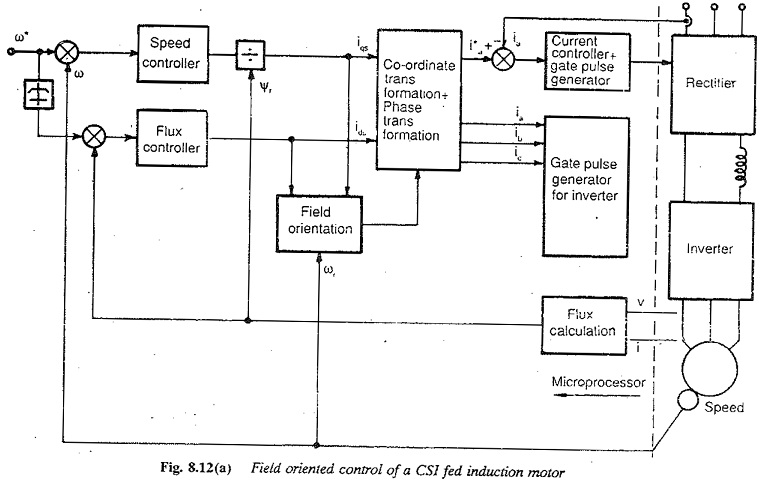
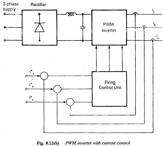
Field orientation is possible with both voltage source inverter as well as current source inverter fed Field Oriented Control of Three Phase Induction Motor. The current source inverter is widely employed due to the simplicity of its power circuit. The features of field oriented control employing CSI are discussed here (8.12(a)). Sometimes a PWM inverter may be controlled suitably to provide the reference currents (Fig. 8.12(b)). This control can be accomplished using a microprocessor.
The flux may be measured directly using search coils or Hall probes. The analog signals are converted to digital ones for feeding into the microprocessor for further processing. This direct measurement, even though theoretically exact, has the following limitations or difficulties: The presence of sensitive Hall probes or search coils make the induction motor more sensitive but its inherent robustness is lost. The measured signal is superimposed by slot harmonics requiring filtering. The errors of measurement and AID conversion make the results rather unreliable. Therefore, normally the computation of the flwc using machine models is employed (indirect estimation).
These machine models for computing the flux make use of the Field Oriented Control of Three Phase Induction Motor parameters determined from no-load and blocked rotor tests. The inaccuracy; of the models in the estimation of the parameters, the variation of machine! parameters due to temperature and saturation must be exactly considered in’ the estimation. The accuracy gets impaired if there is any integration involved in the estimation. This happens if voltage and speed are used in the computation. At low speeds the integration introduces considerable errors in these errors and reliable performance can be achieved over a wide range of speeds down to standstill.
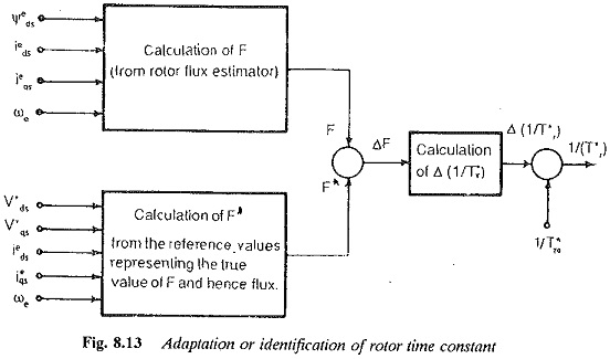
To improve the performance the machine parameters used in the model must be as accurate as possible. Otherwise they can be corrected using a correction process, so that the exact coupling is possible. The correction process upgrades the parameter. The indirect flux estimation along with the so-called parameter identification or adaptation is used to obtain an induction motor with perfect coupling. The flux estimated from the actual sensed variables of current and speed together with the parameters, is compared with the reference value (determined from the reference quantities). The difference is used to correct the machine parameters entering into the calculations. The most influential parameter is the rotor resistance or rotor time constant and it is corrected until the required value of flux is given by the model.
The only solution for field oriented control with parameter adaptation is the use of microprocessors or microcomputers. Several techniques are available in the literature for parameter adaptation. One such scheme is shown in Fig. 8.13. The microprocessor has to perform the mathematical operations to estimate the flux both from the reference values as well as measured variables.
The selection of a microprocessor for the above application may be based on the following considerations:
- Resolution of the firing of the phase controlled rectifier. The resolution decides the asymmetry in the firing.
- The mathematical operations that can be performed. It should be capable of binary and decimal arithmetic, including multiplication and division
- The memory capacity required
- The internal clock generation
- Software support for implementing the controllers, limiters, etc.
- The interrupt capability
Some other applications of a microprocessor in the control of induction motors are:
- A microprocessor may be used to cohtrol the speed using a voltage controller
- It may be used to control the speed using slip energy recovery scheme. Vector control can be employed here also.
- It may be used for the control of slip controlled drive with flux and torque control in CSI fed drives.
- Can be used to implement PWM techniques to control the voltage and harmonics both in VSI and CSI fed induction motors.
- It may be used for cycloconverter control.