Instruction Format of 8085:
Each Instruction Format of 8085 and Data Format of 8085 microprocessor has specific information fields. These information fields of instructions are called elements of instruction. These are :
- Operation code : The operation code field in the instruction specifies the operation to be performed. The operation is specified by binary code, hence the name operation code or simply opcode. For example, for 8085 processor operation code for ADD B instruction is 80H.
- Source / destination operand : The source/destination operand field directly specifies the source/destination operand for the instruction. In the Instruction Format of 8085, the instruction MOV A,B has B register contents as a source operand and A register contents as a destination operand because this instruction copies the contents of register B to register A.
- Source operand address : We know that the operation specified by the instruction may require one or more operands. The source operand may be in the 8085 register or in the memory. Many times the Instruction Format of 8085 specifies the address of the source operand so that operand(s) can be accessed and operated by the 8085 according to the instruction.
In 8085, the source operand address for instruction ADD M is given by HL register pair.
- Destination operand address : The operation executed by the 8085 may produce result. Most of the times the result is stored in one of the operand. Such operand is known as destination operand. The Instruction and Data Format of 8085 which produce result specifies the destination operand address. In 8085, the destination operand address for instruction INR M is given by HL register pair because INR M instruction increments the contents of memory location specified by HL register pair and stores the result in the same memory location.
- Next instruction address : The next instruction address tells the 8085 from where to fetch the next instruction after completion of execution of current instruction. For BRANCH instructions the address of the next instruction is specified within the instruction. However, for other instructions, the next instruction to be fetched immediately follows the current instruction. For example, in 8085, instruction after INR B follows it. The instruction JMP 2000H specifies the next instruction address as 2000H.
Instruction Formats:
The Instruction Format of 8085 set consists of one, two and three byte instructions. The first byte is always the opcode; in two-byte instructions the second byte is usually data; in three byte instructions the last two bytes present address or 16-bit data.
1. One byte instruction :
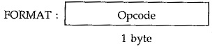
For Example : MOV A, B whose opcode is 78H which is one byte. This Instruction and Data Format of 8085 copies the contents of B register in A register.
2. Two byte instruction :
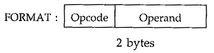
For Example : MVI B, 02H. The opcode for this instruction is 06H and is always followed by a byte data (02H in this case). This instruction is a two byte instruction which copies immediate data into B register.
3. Three byte instruction :
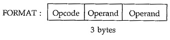
For Example : JMP 6200H. The opcode for this instruction is C3H and is always followed by 16 bit address (6200H in this case). This instruction is a three byte instruction which loads 16 bit address into program counter.
Opcode Format of 8085:
The 8085A microprocessor has 8-bit opcodes. The opcode is unique for each Instruction and Data Format of 8085 and contains the information about operation, register to be used, memory to be used etc. The 8085A identifies all operations, registers and flags with a specific code. For example, all internal registers are identified as shown in the Tables 2.1(a) and 2.2(b).
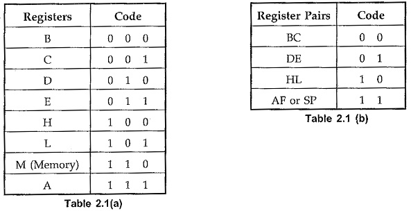
Similarly, there are different codes for each opera are identified as follows :
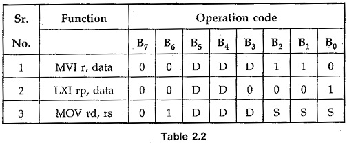
Note : DDD defines the destination register, SSS defines the source register and DD defines the register pair.
Data Format of 8085 Microprocessor:
The operand is an another name for data. It may appear in different forms :
- Addresses
- Numbers/Logical data and
- Characters
Addresses : The address is a 16-bit unsigned integer ,number used to refer a memory location.
Numbers/Data : The 8085 supports following numeric data types.
- Signed Integer : A signed integer number is either a positive number or a negative number. In 8085, 8-bits are assigned for signed integer, in which most significant bit is used for sign and remaining seven bits are used for Sign bit 0 indicates positive number whereas sign bit 1 indicates negative number.
- Unsigned Integer : The 8085 microprocessor supports 8-bit unsigned integer.
- BCD : The term BCD number stands for binary coded decimal number. It uses ten digits from 0 through 9. The 8-bit register of 8085 can store two digit BCD
Characters : The 8085 uses ASCII code to represent characters. It is a 7-bit alphanumeric code that represents decimal numbers, English alphabets, and other special characters.