Multistage Impulse Generator Circuit:
In the early discussion, the generator capacitance C1 is to be first charged and then discharged into the wave shaping circuits. A single capacitor C1 may be used for voltages up to 200 kV. Beyond this voltage, a single capacitor and its charging unit may be too costly, and the size becomes very large. The cost and size of the impulse generator increases at a rate of the square or cube of the voltage rating. Hence, for producing very high voltages, a bank of capacitors are charged in parallel and then discharged in series. The arrangement for charging the capacitors in parallel and then connecting them in series for discharging was originally proposed by Man. Nowadays modified Marx circuits are used for the Multistage Impulse Generator Circuit.
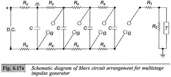
The schematic diagram of Marx circuit arrangement for Multistage Impulse Generator Circuit and its modification are shown in Figs 6.17a and 6.17b, respectively. Usually the charging resistance Rs is chosen to limit the charging current to about 50 to 100 mA, and the generator capacitance C is chosen such that the product CRs is about 10 s to 1 min. The gap spacing is chosen such that the breakdown voltage of the gap G is greater than the charging voltage V. Thus, all the capacitance are charged to the voltage V in about 1 minute.
where
C – Capacitance of the generator
Rs – Charging resistors
G – Spark gap
R1,R2 – Wave shaping resistors
T – Test object
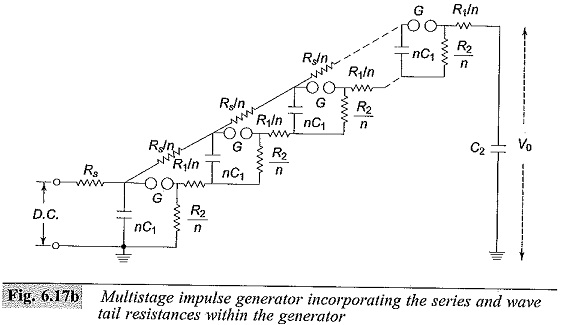
When the impulse generator is to be discharged, the gaps G are made to spark over simultaneously by some external means. Thus, all the capacitors C get connected in series and discharge into the load capacitance or the test object. The discharge time constant CR1/n (for n stages) will be very very small (microseconds), compared to the charging time constant CRs which will be few seconds. Hence, no discharge takes place through the charging resistors Rs. In the Marx circuit is of Fig. 6.17a the impulse wave shaping circuit is connected externally to the capacitor unit. In Fig. 6.17b, the modified Marx circuit is shown, wherein the resistances R1 and R2 are incorporated inside the unit. R1 is divided into n parts equal to R1/n and put in series with the gap G. R2 is also divided into n parts and arranged across each capacitor unit after the gap G. This arrangement saves space, and also the cost is reduced. But, in case the waveshape is to be varied widely, the variation becomes difficult. The additional advantages gained by distributing R1 and R2 inside the unit are that the control resistors are smaller in size and the efficiency (V0/nV) is high.
Impulse generators are nominally rated by the total voltage (nominal), the number of stages, and the gross energy stored. The nominal output voltage is the number of stages multiplied by the charging voltage. The nominal energy stored is given by 1/2 C1V2 where C1 = C/n (the discharge capacitance) and V is the nominal maximum voltage (n times charging voltage). A 16-stage impulse generator having a stage capacitance of 0.280 μF and a maximum charging voltage of 300 kV will have an energy rating of 192 kW sec. The height of the generator will be about 15 in and will occupy a floor area of about 3.25 x 3.00 m. The waveform of either polarity can be obtained by suitably changing the charging unit polarity (Plate 3).
Components of a Multistage Impulse Generator Circuit:
A Multistage Impulse Generator Circuit requires several components parts for flexibility and for the production of the required waveshape. These may be grouped as follows:
1.d.c. Charging Set: The charging unit should be capable of giving a variable d.c. voltage of either polarity to charge the generator capacitors to the required value.
2.Charging Resistors: These will be non-inductive high value resistors of about 10 to 100 kilo-ohms. Each resistor will be designed to have a maximum voltage between 50 and 100 kV.
3.Generator Capacitors and Spark Gaps: These are arranged vertically one over the other with all the spark gaps aligned. The capacitors are designed for several charging and discharging operations. On dead short circuit, the capacitors will be capable of giving 10 kA of current. The spark gaps will be usually spheres or hemispheres of 10 to 25 cm diameter. Sometimes spherical ended cylinders with a central support may also be used.
4.Wave-shaping Resistors and Capacitors: Resistors will be non-inductive wound type and should be capable of discharging impulse currents of 1000 A or Each resistor will be designed for a maximum voltage of 50 to 100 kV. The resistances are bifilar wound on non-inductive thin flat insulating sheets. In some cases, they are wound on thin cylindrical formers and are completely enclosed. The load capacitor may be of compressed gas or oil filled with a capacitance of 1 to 10 nF.
Modern impulse generators have their wave-shaping resistors included internally with a flexibility to add additional resistors outside, when the generator capacitance is changed (with series parallel connection to get the desired energy rating at a given test voltage). Such generators optimize the set of resistors. A commercial impulse voltage generator uses six sets of resistors ranging from 1.0 ohm to about 160 ohms with different combinations (with a maximum of two resistors at a time) such that a resistance value varying from 0.7 ohm to 235 ohms per stage is obtained, covering a very large range of energy and test voltages. The resistors used are usually resin cast with voltage and energy ratings of 200 to 250 kV and 2.0 to 5.0 kWsec. The entire range of lightning and switching impulse voltages can be covered using these resistors either in series or in parallel combination.
5.Triggering System: This consists of trigger spark gaps to cause spark breakdown of the gaps.
6.Voltage Dividers: Voltage dividers of either damped capacitor or resistor type and an oscilloscope with recording arrangement are provided for measurement of the voltages across the test object. Sometimes a sphere gap is also provided for calibration purposes.
7.Gas insulated impulse generators: Impulse generators rated for 4 MV or above will be very tall and require large space. As such they are usually located in open space and are housed in an insulated enclosure. The height of a 4.8 MV unit may be around 30 m. To make the unit compact, a compressed gas, such as N2 or SF6 may be used as the insulation.
Impulse generators are needed to generate very fast transients having time duration of 0.5/5 or 0.1/1.0 μs waves for testing Gas Insulated Systems (GIS) that are coming up nowadays. The energy needed for testing of this type of equipment is small (less than 30 kJ) and the load capacitance is usually less than 500 pF.