Measurements of Thickness using Beta Gauge:
Beta Gauge – A common and characteristic feature of a radioactive element is that they disintegrate spontaneously to produce fresh radioactive elements called daughter elements. This activity of parent elements is termed as radioactivity.
During this disintegration, high energy radiations are emitted from the nuclear of the radioactive element. These high energy radiations are mostly of three types: the positively charged rays called alpha (α) rays, the negatively charged rays called beta (β) rays, and the neutral rays called gamma (γ) rays. β rays are usually, but not necessarily accompanied by (γ) rays.
Some of the basic and important properties of α, β, and γ-rays are listed in Table 13.5
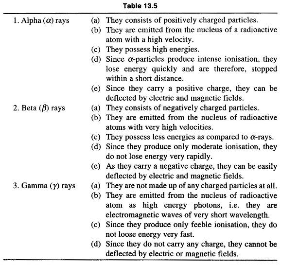
Alpha rays are not used in radio metrical measurement techniques because their range is only some mm, even in air. Hence this leaves only beta and gamma radiations.
Measuring Principle of Beta Gauge:
The measurement of the weight/unit area of the sheet material is accomplished by measuring the absorption of radiation emanating from a radio isotope when passing through the material. If the material is homogeneous and its density is known, the wt/unit area measurement can be transformed into a thickness measurement.
Mode of Operation:
Figure 13.61 shows a schematic block diagram of a Beta Gauge.
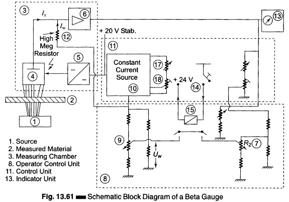
The source (1), enclosed in a source holder, is positioned to one side of the material to be measured (2) The measuring chamber (3), containing an ionisation chamber as the detector, is located exactly opposite the source, on the other side of the material. Part of the radiation from the source is absorbed during the passage through the material, and the remaining radiation ionises the gas in the ionisation chambers. A dc converter (5) supplies the anode of the ionisation chamber with high voltage. The resulting field causes an ionisation current Ix, proportional to the intensity of the received radiation. This current is collected by the measuring electrode.
The capacitor-diode amplifier (6), is a dc amplifier with high input impedance and low leakage. In its feedback loop, the voltages from the feedback divider (7), located in the operator control unit (8) and the target value adjust (9), are effective. The target value adjust is calibrated such that the voltage applied to the high-meg resistor of the measuring chamber causes a current Iw equal and opposite in polarity to the ionisation current Ix. If the measured wt/unit area or thickness of the material in the measuring gap is on target, the voltage at the amplifier output connected to the deviation indicator input goes to zero.
Deviations of the measured product from the target cause the indicator to move towards plus or minus proportional to the magnitude of the error.
Full radiation is used for balancing the system, i.e. no material in the measuring gap. By pushing the full radiation button (14) in the control unit (11), the feedback loop is connected via a relay (15) to a compensation voltage equivalent to zero weight or no material (product) in the measuring gap. The deviation indicator (13) should be moved to zero by actuating the coarse switch and adjusting the fine potentiometer. This adjusts both the feedback voltage and current Iw to match the ionisation current.
Measuring Chamber:
The measuring chamber which mentioned in Beta Gauge is utilized for measuring base weight or thickness by absorption of radioactive radiation.
It is dust tight, with ambient temperature ranges from +10°C – +50 °C. The influence of the temperature of the air in the measuring gap on the measurement is compensated for by the temperature compensation circuit. The ionisation current causes a voltage drop across the high-meg resistors. The difference between this voltage drop and the compensation voltage is amplified by a two-stage capacitor-diode amplifier.
Control Unit:
The control unit supplies the voltage for the measuring chamber. It contains the master switch and the elements for balancing are equipped with automatic temperature compensation, i.e. compensation of wt/unit area caused by temperature changes of the air in the measuring gap.
This system requires the following voltages: 24 V ac and +24 V dc stabilized. 24 V ac is tapped from a separate winding of the power transformer. A separate winding also supplies the circuit protected stabilized power supply + 24 V dc and 0.7 A.
A constant current source supplies the operator control unit. The target value potentiometer in this unit sets the comparator voltage for the measuring chamber. Since the constant current source must be floating, an electronic chopper is employed to supply its regulator.
The temperature compensation circuit, if supplied, adjusts for temperature related changes of wt/unit area of the air in the measuring gap. It does this by feeding an error voltage to the constant current source. This voltage is generated by an IC amplifier in a bridge circuit one of whose branches contains temperature sensors (NTC) of the measuring chamber and the source holder.
Balancing, i.e. compensation for a source decay, is accomplished by adjusting the constant current and the feedback voltage derived from the measured value to match the compensation voltage of the measuring chamber proportional to the source decay.
Control Sequence of the Motion of the Measuring Heads:
The control of the measuring head motion is possible in various program sequences such as (i) automatic profile scanning, (ii) traversing scanning, (iii) jugging, (iv) off-sheet position, and (v) test position.
1.Automatic Profile Scanning:
After pressing the profile push button, the measuring head leaves the off-sheet position Ea, as shown in Fig. 13.62, passes the limit switch at the left side sheet edge Eb and stops at the permanent measuring position Ed. Presetting this button again, or after making contact with the preset time switch mechanism initiates the automatic profile scanning. The measuring head moves at high speed to the right side Er, then back to the left side edge at low speed and returns at high speed to the center positions Ed. It records only at low speed.

2.Traversing:
This program constitutes a pendular movement of the measuring head, between two limit switches El and Er, whereby the traversing speed from the right side to the left side can be determined by converting the bridges, released by pressing the traverse button.
3.Jugging:
At jugging, an optimal positioning of the measuring head between the limit switches Ea and Er is possible.
4.Off-sheet Movement:
Off-sheet movement to the limit switch Ea can be effected by various command inputs, either by pressing the push-button off-sheet movement at the control panel, or by means of the adjustment command from the power supply unit.
5.Test Position:
This limit switch is situated outside the right side turning point Er and can be reached by the Test Position button.