Working Principle of Automatic Gain Control:
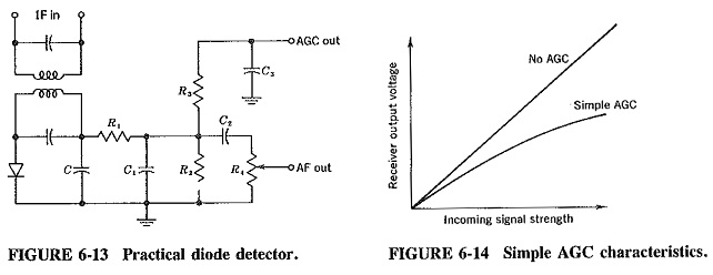
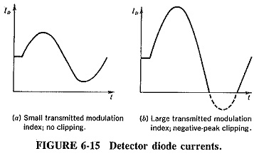
Working Principle of Automatic Gain Control is a system by means of which the overall gain of a radio receiver is varied automatically with the changing strength of the received signal, to keep the output substantially constant. A de bias voltage, derived from the detector as shown and explained in connection with Figure 6-13, is applied to a selected number of the RF, IF and mixer stages. The devices used in those stages are ones whose transconductance and hence gain depends on the applied bias voltage or current. It may be noted in passing that, for correct AGC operation, this relationship between applied bias and transconductance need not be strictly linear, as long as transconductance drops significantly with increased bias. The overall result on the receiver output is seen in Figure 6-14.
All modern receivers are furnished with Working Principle of Automatic Gain Control, which enables tuning to stations of varying signal strengths without appreciable change in the volume of the output signal. Thus AGC “irons out” input signal amplitude variations, and the gain control does not have to be readjusted every time the receiver is tuned from one station to another, except when the change in signal strengths is enormous. In addition, Working Principle of Automatic Gain Control helps to smooth out the rapid fading which may occur with long-distance shortwave reception and prevents overloading of the last IF amplifier which might otherwise have occurred.
Simple AGC in bipolar transistor receivers:
The significant difference between FET and bipolar transistor receivers, from the point of view of Working Principle of Automatic Gain Control application, is that in the bipolar case bias current is fed back, so that some power is required. Various methods are used for the application AGC in transistor receivers. A common one is analogous to that once employed in tube circuits, in that the gain of the relevant amplifiers is controlled by the adjustment (with AGC bias current) of emitter current.
The emitter current is most easily controlled by variation of the base current, provided that sufficient AGC power is available. Since this power must be larger if the stage to be controlled has been stabilized against slow collector current variation, it is preferable to make this stabilization less effective in a stage controlled by AGC. The method of applying automatic gain control of this type is shown at the base of the “first IF amplifier” in Figure 6-11.
It is possible to increase the available control power by using dc amplification after the detector. Whereas a separate amplifier would be employed for this purpose in an elaborate receiver, the first audio amplifier is much more likely to be used in a broadcast receiver. In such an arrangement, the first AF amplifier must be dc-coupled, in which case care must be taken to ensure that its bias is not upset unduly; otherwise, the amplifier will distort.
Distortion in diode detectors:
Two types of distortion may arise in diode detectors. One is caused by the ac and dc diode load impedance being unequal, and the other by the fact that the ac load impedance acquires a reactive component at the highest audio frequencies.
Just as modulation index of the modulated wave was defined as the ratio Vm/Vc in Equation (3-4) and Figure 3-1, so the modulation index in the demodulated wave is defined as

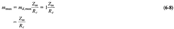
The two currents are shown in Figure 6-15, and it is to be noted that the definition is in terms of currents because the diode is a current-operated device. Bearing in mind that all these are peak (rather than rms) values, we see that

where
Zm = audio diode load impedance, as described previously, and is assumed to be resistive
Rc = dc diode load resistance
The audio load resistance is smaller than the dc resistance. Hence it follows that the AF current Im will be larger, in proportion to the dc current, than it would have been if both load resistances had been exactly the same. This is another way of saying that the modulation index in the demodulated wave is higher than it was in the modulated wave applied to the detector. This, in turn, suggests that it is possible for over-modulation to exist in the output of the detector, despite a modulation index of the applied voltage of less than 100 percent. The resulting diode output current, when the input modulation index is too high for a given detector, is shown in Figure 6-15b.
It exhibits negative peak clipping. The maximum value of applied modulation index which a diode detector will handle without negative peak clipping is calculated as follows:
The modulation index in the demodulated wave will be

Since the maximum tolerable modulation index in the diode output is unity, the maximum permissible transmitted modulation index will be
Because the modulation percentage in practice (in a broadcasting system at any rate) is very unlikely to exceed 70 percent, this can be considered a well-designed detector. Since bipolar transistors may have a rather low input impedance, which would be connected to the wiper of the volume control and would therefore load it and reduce the diode audio load impedance, the first audio amplifier could well be made a field-effect transistor. Alternatively, a resistor may be placed between the moving contact of the volume control and the base of the first transistor, but this unfortunately reduces the voltage fed to this transistor by as much as a factor of 5.
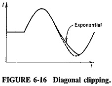
Diagonal clipping is the name given to the other form of trouble that may arise with diode detectors. At the higher modulating frequencies, Zm may no longer be purely resistive; it can have a reactive component due to C and C1. At high modulation depths current will be changing so quickly that the time constant of the load may be too slow to follow the change. As a result, the current will decay exponentially, as shown in Figure 6-16, instead of following the waveform. This is called diagonal clipping. It does not normally occur when percentage modulation (at the highest modulation frequency) is below about 60 percent, so that it is possible to design a diode detector that is free from this type of distortion. The student should be aware of its existence as a limiting factor on the size of the RF filter capacitors.