Wien Bridge Circuit Diagram:
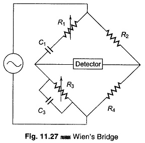
The Wien Bridge Circuit Diagram shown in Fig. 11.27 has a series RC combination in one arm and a parallel combination in the adjoining arm. Wien’s bridge in its basic form, is designed to measure frequency. It can also be used for the measurement of an unknown capacitor with great accuracy.
The impedance of one arm is
![]()
The admittance of the parallel arm is
![]()
Using the bridge balance equation,
we have
![]()
Therefore,
![]()
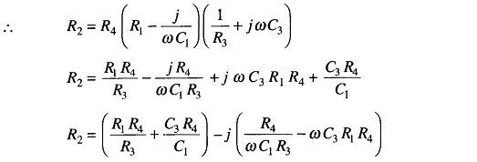
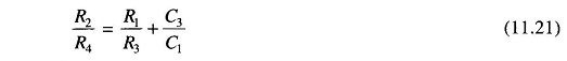
Equating the real and imaginary terms we have

Therefore
and
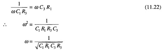
as
![]()
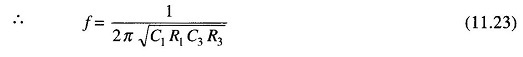
The two conditions for bridge balance, (11.21) and (11.23), result in an expression determining the required resistance ratio R2/R4 and another expression determining the frequency of the applied voltage. If we satisfy Eq. (11.21) and also excite the bridge with the frequency of Eq. (11.23), the bridge will be balanced.
In most Wien Bridge Circuit Diagram, the components are chosen such that R1 = R3 = R and C1 = C3 = C. Equation (11.21) therefore reduces to R2/R4 = 2 and Eq. (11.23) to f = ½πRC, which is the general equation for the frequency of the bridge circuit.
The bridge is used for measuring frequency in the audio range. Resistances R1 and R3 can be ganged together to have identical values. Capacitors C1 and C3 are normally of fixed values.
The audio range is normally divided into 20 – 200 – 2 k – 20 kHz ranges. In this case, the resistances can be used for range changing and capacitors C1 and C3 for fine frequency control within the range. The Wien Bridge Circuit Diagram can also be used for measuring capacitances. In that case, the frequency of operation must be known.
The bridge is also used in a harmonic distortion analyzer, as a Notch filter, and in audio frequency and radio frequency oscillators as a frequency determining element.
An accuracy of 0.5% – 1% can be readily obtained using this bridge. Because it is frequency sensitive, it is difficult to balance unless the waveform of the applied voltage is purely sinusoidal.