Wideband Antenna Types:
It is often desirable to have an antenna capable of operating over a wide frequency range. This may occur because a number of widely spaced channels are used, as in short-wave transmission or reception, or because only one channel is used (but it is wide), as in television transmission and reception. In TV reception, the requirement for Wideband Antenna Types properties is magnified by the fact that it is desirable to use the same receiving antenna for a group of neighboring channels. A need exists for Wideband Antenna Types whose radiation pattern and input impedance characteristics remain constant over a wide frequency range.
Of the antennas discussed so far, the horn (with or without paraboloid reflector), the rhombic and the folded dipole exhibit broadband properties for both impedance and radiation pattern. This was stated at the time for the first two, but the folded dipole will now be examined from this new point of view.
The special Wideband Antenna Typess to be described include the discone, helical and log-periodic antennas, as well as some of the simpler loops used for direction finding.
Folded Dipole (Bandwidth Compensation):
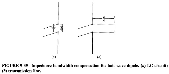
A simple compensating network for increasing the bandwidth of a dipole antenna is shown in Figure 9-39a. The LC circuit is parallel-resonant at the half-wave dipole resonant frequency. At this frequency its impedance is, therefore, a high resistance, not affecting the total impedance seen by the transmission line. Below this resonant frequency the antenna reactance becomes capacitive, while the reactance of the LC circuit becomes inductive. Above the resonant frequency the opposite is true, the antenna becoming inductive, and the tuned circuit capacitive. Over a small frequency range near resonance, there is thus a tendency to compensate for the variations in Wideband Antenna Types reactance, and the total impedance remains resistive in situations in which the impedance of the antenna alone would have been heavily reactive. This compensation is both improved and widened when the Q of the resonant circuit is lowered. Moreover, it can be achieved just as easily with a short-circuited quarter-wave transmission line, as in Figure 9-39b. The folded dipole provides the same type of compensation as the transmission-line version of this network.
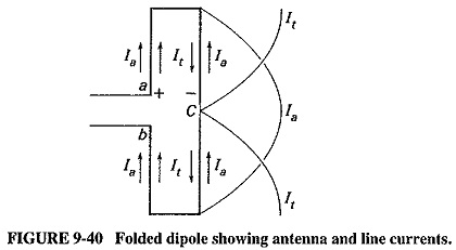
Reference to Figure 9-40 shows that the folded dipole may be viewed as two short-circuited, quarter-wave transmission lines, connected together at C and fed in series. The transmission line currents are labeled It, whereas the antenna currents are identical to those already shown for a straight half-wave dipole and are labeled la. When a voltage is applied at a and b, both sets of currents flow, but the antenna currents are the only ones contributing to the radiation. The transmission-line currents flow in opposite directions, and their radiations cancel. However, we do have two short-circuited quarter-wave transmission lines across a – b, and, explained in the preceding paragraph, the antenna impedance will remain resistive over a significant frequency range. Indeed, it will remain acceptable over a range in excess of 10 percent of the center frequency.
It should be noted that the Wideband Antenna Types is useless at twice the frequency. This is because the short-circuited transmission-line sections are each a half-wavelength long now, short-circuiting the feed point. Note also that the Yagi-Uda antenna is similarly broadband, since the driven element is almost always a folded dipole.
Helical Antenna:
A helical antenna, illustrated in Figure 9-41, is a broadband VHF and UHF antenna which is used when it is desired to provide circular polarization characteristics.
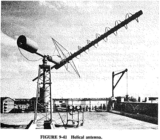
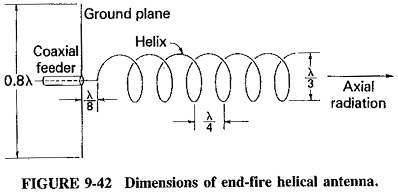
The Wideband Antenna Types consists of a loosely wound helix backed up by a ground plane, which is simply a screen made of “chicken” wire. There are two modes of radiation, normal (meaning perpendicular) and axial. In the first, radiation is in a direction at right angles to the axis of the helix. The second mode produces a broadband, fairly directional radiation in the axial direction. If the helix circumference approximates a wavelength, it may be shown that a wave travels around the turns of the helix, and the radiant lobe in this end-fire action is circularly polarized. Typical dimensions of the antenna are indicated in Figure 9-42.
When the helical antenna has the proportions shown, it has typical values of directivity close to 25, beamwidth of 90° between nulls and frequency range of about 20 percent on either side of center frequency. The energy in the circularly polarized wave is divided equally between the horizontal and vertical components; the two are 90° out of phase, with either one leading, depending on construction. The transmission from a circularly polarized antenna will be acceptable to vertical or horizontal antennas, and similarly a helical antenna will accept either vertical or horizontal polarization.
The helical antenna is used either singly or in an array for transmission and reception of VHF signals through the ionosphere, as has already been pointed out. It is thus frequently used for satellite and probe communications, particularly for radio-telemetry.
When the helix circumference is very small compared to a wavelength, the radiation is a combination of that of a small dipole located along the helix axis, and that of a small loop placed at the helix turns (the ground plane is then not used). Both such antennas have identical radiation patterns, and they are here at right angles, so that the normal radiation will be circularly polarized if its two components are equal, or elliptically polarized if one of them predominates.
Discone Antenna:
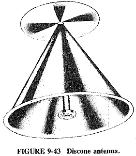
Pictured in Figure 9-43, the discone antenna is as the name aptly suggests, a combination of a disk and a cone in close proximity. It is a ground plane antenna evolved from the vertical dipole and having a very similar radiation pattern. Typical dimensions are shown in Figure 9-44, where D = λ/4 at the lowest frequency of operation.
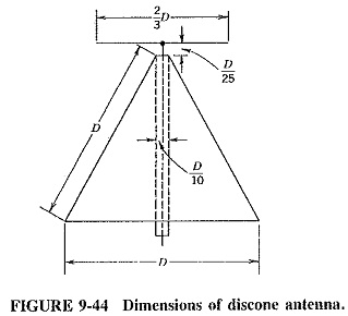
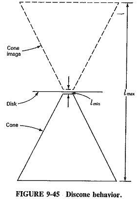
The discone antenna is characterized by an enormous bandwidth for both input impedance and radiation pattern. It behaves as though the disk were a reflector. As shown in Figure 9-45, there is an inverted cone image above the disk, reflected by the disk. Now consider a line perpendicular to the disk, drawn from the bottom cone to the top image cone. If this line is moved to either side of the center of the disk, its length will vary from a minimum at the center (lmin) to a maximum at the edge (lmax) of the cone. The frequency of operation corresponds to the range of frequencies over which this imaginary line is a half-wavelength, and it can be seen that the ratio of lmin to lmax is very large. The discone is thus a broadband antenna because it is a constant-angle antenna. For the proportions shown in Figure 9-44, the SWR on the coaxial cable connected to the discone antenna can remain below 1.5 for a 7:1 frequency range. Overall performance is still satisfactory for a 9:1 frequency ratio.
The discone is a low-gain antenna, but it is omnidirectional. It is often employed as a VHF and UHF receiving and transmitting antenna, especially at airports, where communication must be maintained with aircraft that come from any direction. More recently, it has also been used by amateurs for reception in the HF band, in which case it is made of copper or aluminum wire, along the lines of an upside-down waste basket. A typical frequency range, under these conditions, may be 12 to 55 MHz.
Log-Periodic Antennas:
Log-periodic antennas are a class of antennas which vary widely in physical appearance. Log-periodics are more recent than most antennas, having been first proposed in 1957. Their main feature is frequency independence for both radiation resistance and pattern. Bandwidths of 10:1 are achievable with ease. The directive gains obtainable are low to moderate, and the radiation patterns may be uni- or bidirectional.
It is not possible to cover all log-periodic antennas here. The most common one, the log-periodic dipole array of Figure 9-46, will be discussed. This can also be used to introduce the characteristics of log-periodic antennas.
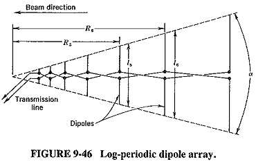
It is seen that there is a pattern in the physical structure, which results in a repetitive behavior of the electrical characteristics. The array consists of a number of dipoles of different lengths and spacing, fed from a two-wire line which is transposed between each adjacent pair of dipoles. The array is fed from the narrow end, and maximum radiation is in this direction, as shown. The dipole lengths and separations are related by the formula

where τ (torsion of a curve) is called the design ratio and is a number less than 1. It is seen that the two lines drawn to join the opposite ends of the dipoles will be straight and convergent, forming an angle α (varies directly). Typical design values may be τ = 0.7 and α = 30°. As with other Wideband Antenna Types, these two design parameters are not independent of each other. The cutoff frequencies are approximately those at which the shortest and longest dipoles have a length of λ/2. (Note the similarity to the discone antenna!)
If a graph is drawn of the antenna input impedance (or SWR on the feed line) versus frequency, a repetitive variation will be noticed. If the plot is made against the logarithm of frequency, instead of frequency itself, this variation will be periodic, consisting of identical, but not necessarily sinusoidal, cycles. All the other properties of the antenna undergo similar variations, notably the radiation pattern. It is this behavior of the log-periodic antenna that has given rise to its name.
Like those of the rhombic, the applications of the log-periodic antenna lie mainly in the field of high-frequency communications, where such multiband steerable and fixed antennas are very often used. It has an advantage over the rhombic in that there is no terminating resistor to absorb power. Antennas of this type have also been designed for use in television reception, with one antenna for all channels including the UHF range. It must be reiterated that the log-periodic dipole array is but one of a large number of antennas of this class—there are many other exotic-looking designs, including arrays of log-periodics.
Loop Antennas:
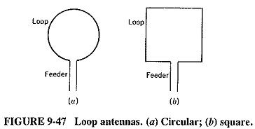
A loop antenna is a single-turn coil carrying RF current. Since its dimensions are nearly always much smaller than a wavelength, current throughout it may be assumed to be in phase. Thus the loop is surrounded by a magnetic field everywhere perpendicular to the loop. The directional pattern is independent of the exact shape of the loop and is identical to that of an elementary doublet. The circular and square loops of Figure 9-47.have the same radiation pattern as a short horizontal dipole, except that, unlike a horizontal dipole, a vertical loop is vertically polarized.
Because the radiation pattern of the loop antenna is the familiar doughnut pattern, no radiation is received that is normal to the plane of the loop. This, in turn, makes the loop antenna suitable for direction finding (DF) applications. For DF, it is required to have an antenna that can indicate the direction of a particular radiation. Although any of the highly directional antennas of the previous section could be used for this purpose (and are, in radar), for normal applications they have the disadvantage of being very large, which the loop is not. The DF properties of the loop are just as good at medium frequencies as those of the directional microwave antennas, except that the gain is not comparable. Also, the direction of a given radiation corresponds to. a null, rather than maximum signal. Because the loop is small, and DF equipment must often be portable, loops have direction finding as their major application.
A small loop, vertical and rotatable about a vertical axis, may be mounted on top of a portable receiver whose output is connected to a meter. This makes a very good simple direction finder. Having tuned to the desired transmission, it is then necessary to rotate the loop until the received signal is minimum, The plane of the loop is now perpendicular to the direction of the radiation. Since the loop is bidirectional, two bearings are required to determine the precise direction. If the distance between them is large enough, the distance of the source of this transmission may be found by calculation.
There are a large number of variations on the theme of the loop, far too many to consider here. They include the Alford loop, cloverleaf, Adcock antenna, and the Bellini-Tosi antenna.
Loops are sometimes provided with several turns and also with ferrite cores, these, being magnetic, increase the effective diameter of the loop. Such antennas are commonly built into portable broadcast receivers. The Wideband Antenna Types configuration explains why, if a receiver tuned to any station is rotated, a definite null will be noticed.
Phased Arrays:
A phased array is a group of antennas, connected to the one transmitter or receiver, whose radiation beam can be adjusted electronically without any physically moving parts. Moreover, this adjustment can be very rapid indeed. More often than not, transmission or reception in several directions at once is possible. The antennas may be actual radiators, e.g., a large group of dipoles in an array (or array of arrays) pointing in the general wanted direction, or they may be the feeds for a reflector of some kind.
There are two basic types of phased arrays. In the first, a single, high-power output tube (in a transmit phased array) feeds a large number of antennas through a set of power dividers and phase shifters. The second type uses generally as many (semiconductor) generators as there are radiating elements. The phase relation between the generators is maintained through phase shifters, but this time they are low-power devices. In both types of phased arrays the direction of the beam or beams is selected by adjusting the phase difference provided by each phase shifter. This is generally done with the aid of a computer or microprocessor.
The main application of phased arrays is in radar It is worth noting that phased arrays have recently been considered for satellite communications.