Waveguide Junctions:
When it is required to combine two or more signals (or split a signal into two or more parts) in a waveguide system, some form of multiple junction must be used. For simpler interconnections T-shaped junctions are used, whereas more complex junctions may be hybrid T or hybrid rings. In addition to being Waveguide Junctions, these components also have other applications, and hence they will now be described in some detail.
T junctions:
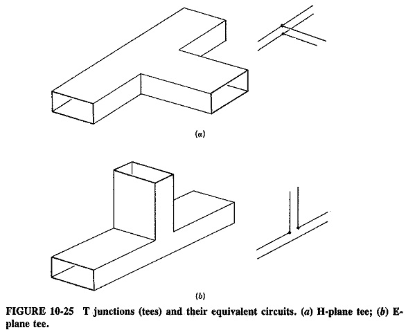
Two examples of the T junction, or tee, are shown in Figure 10-25, together with their transmission-line equivalents. Once again they are referred to as E-or H-plane trees, depending on whether they are in the plane of the electric field or the magnetic field.
All three atoms of the H-plane tee lie in the plane of the magnetic field, which divides among the arms. This is a current junction, i.e., a parallel one, as shown by the transmission-line equivalent circuit. In a similar way, the E-plane tee is a voltage or series junction, as indicated. Each Waveguide Junctions is symmetrical about the central arm, so that the signal to be split up is fed into it (or the signals to be combined are taken from it). However, some form of impedance matching is generally required to prevent unwanted reflections.
T junctions (particularly the E-plane tee) may themselves be used for impedance matching, in a manner identical to the short-circuited transmission-line stub. The vertical arm is then provided with a sliding piston to produce a short circuit at any desired point.
Hybrid junctions:
If another arm is added to either of the T junctions, then a hybrid T junction, or magic tee, is obtained; it is shown in Figure 10-26. Such a Waveguide Junctions is symmetrical about an imaginary plane bisecting arms 3 and 4 and has some very useful and interesting properties.
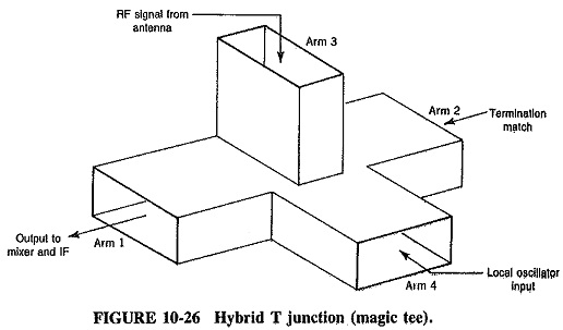
The basic property, is that arms 3 and 4 are both connected to arms 1 and 2 but not to each other. This applies for the dominant mode only, provided each arm is terminated in a correct load.
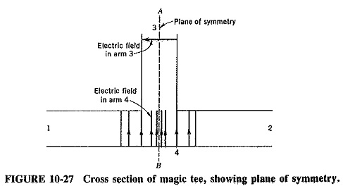
If a signal is applied to arm 3 of the magic tee, it will be divided at the Waveguide Junctions, with some entering arm 1 and some entering arm 2, but none will enter arm 4. This may be seen with the aid of Figure 10-27, which shows that the electric field for the dominant mode is evenly symmetrical about the plane A-B in arm 4 but is unevenly symmetrical about plane A-B in arm 3 (and also in arms 1 and 2, as it happens). That is to say, the electric field in arm 4 on one side of A-B is a mirror image of the electric field on the other side, but in arm 3 a phase change would be required to give such even symmetry. Since nothing is there to provide such a phase change, no signal applied to arm 3 can propagate in arm 4 except in a mode with uneven symmetry about the plane A-B (such as a TE0,1 or TM1,1). The dimensions being such as to exclude the propagation of these higher modes, no signal travels down arm 4. Because the arrangement is reciprocal, application of a signal into arm 4 likewise results in no propagation down arm 3.
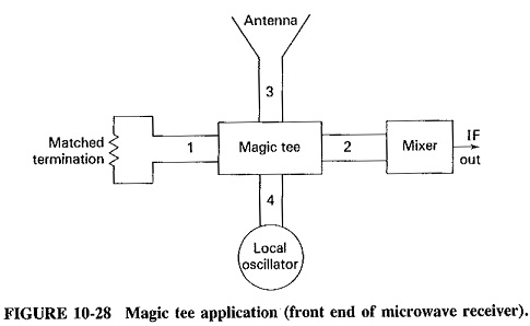
Since arms 1 and 2 are symmetrically disposed about the plane A-B, a signal entering either arm 3 or arm 4 divides evenly between these two lateral arms if they are correctly terminated. This means that it is possible to have two generators feeding signals, one into arm 3 and the other into arm 4. Neither generator is coupled to the other, but both are coupled to the load which, in Figure 10-28, is in arm 2, (while arm 1 has a matched termination connected to it). The arrangement shown is but one of a number of applications of the magic tee.
It should be noted that quite bad reflections will take place at the Waveguide Junctions unless steps are taken to prevent them. From a transmission-line viewpoint, arm 3 sees an open circuit in place of arm 4 and, across this infinite impedance, it also sees two correctly matched impedance in parallel. To avoid the resulting mismatch, two obstacles are normally placed at the Waveguide Junctions, in the form of a post and an iris.
Figure 10-29 shows a waveguide arrangement which looks quite different from the hybrid T and yet has very similar functions; it is the hybrid ring, or rat race. The arrangement consists of a piece of rectangular waveguide, bent in the E plane to form a complete loop whose median circumference is 1.5λp. It has four orifices, with separation distances as shown in Figure 10-296, from each of which a waveguide emerges. If there are no reflections from the terminations in any of the arms, any one arm is coupled to two others but not to the fourth one.
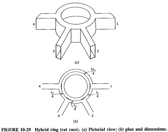
If a signal is applied to arm 1, it will divide evenly, with half of it traveling clockwise and the other half counterclockwise. The signal reaching arm 4 will cover the same distance, whether it has traveled clockwise or counterclockwise, and addition will take place at that point, resulting in some signal traveling down arm 4. Similarly, a signal reaching the input of arm 2 will have traveled a distance of λp/4 if traveling clockwise, and 1 1/4 λp if traveling counterclockwise. The two portions of signal will add at that point, and propagation down arm 2 will take place. The signal at the mouth of arm 3 will have traveled a distance of λp/2 going one way and λp going the other, so that these two out-of-phase portions will cancel, and no signal will enter arm 3. In a similar way, it may be shown that arm 3 is connected to arms 2 and 4, but not to arm 1. It is thus seen that behavior is very similar to that of the magic tee, although for a different reason.
The rat race and the magic tee may be used interchangeably, with the latter having the advantage of smaller bulk but the disadvantage of requiring internal matching. This is not necessary in the rat race if the thickness of the ring is correctly chosen. The hybrid ring seems preferable at shorter wavelengths, since its dimensions are less critical.