Unbalanced Source Voltages Operations:
As Supply voltage may sometimes become unbalanced, it is useful to know the effect of Unbalanced Source Voltages Operations on motor performance. Further, motor terminal voltage may be unbalanced intentionally for speed control or starting as described later.
A three-phase set of Unbalanced Source Voltages Operations (Va,Vb and Vc) can be resolved into three-phase balanced positive sequence (Vp), negative sequence (Vn) and zero sequence (V0) voltages, using symmetrical component relations:
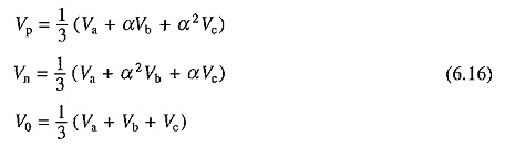
where
![]()
Positive sequence voltages have the same phase sequence as original system, and negative sequence voltages have opposite phase sequence. It will be assumed here that machine does not have a neutral connection. In the absence of a neutral connection, zero sequence line voltage becomes zero.
Motor performance can be calculated for positive and negative sequence voltages separately. Resultant performance is obtained by the principle of superposition by assuming motor to be a linear system.
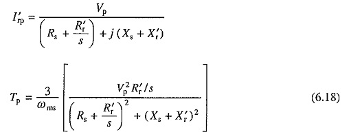
Positive sequence voltages produce an air-gap flux wave which rotates at synchronous speed in the forward direction. For a forward rotor speed ωm, slip s is given by Eq. (6.1). For positive sequence voltages, equivalent circuits are same as shown in Fig. 6.1, except that V is replaced by Vp. The positive sequence rotor current and torque are obtained by replacing V by Vp, in Eqs. (6.4) and (6.10). Thus
Negative sequence voltages produce an air-gap flux wave which rotates at synchronous speed in the reverse direction. The slip is
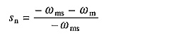
Substitution from Eq. (6.3) gives
![]()
Again, equivalent circuits of Fig. 6.1 are applicable when s is replaced by (2 — s) or sn, and V are replaced by Vn. Proceeding as in Sec. 6.1, following expressions are obtained for rotor current and torque:
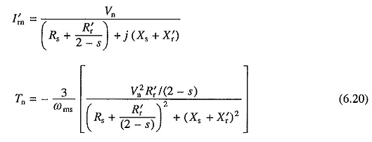
Torque has a negative sign because for negative sequence voltages the synchronous speed is (-ωms).
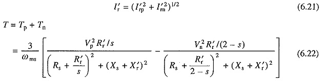
The rms rotor current and torque are given by
Positive sequence, negative sequence and the resultant speed-torque characteristics are shown in Fig. 6.4(a).
Single phasing (when supply to any one phase fails) is the extreme case of unbalancing, when
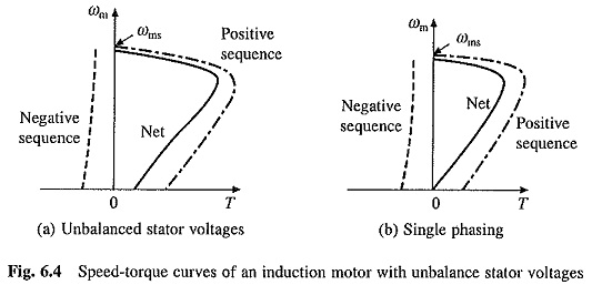
Vp = Vn. At zero speed, s is also equal to sn, consequently starting torque is zero. Speed-troque curves for single phasing are shown in Fig. 6.4(b). For analysis of star connected machine under single phasing, method of analysis described in Sec. 6.6.3 for ac dynamic braking with two lead connection and equivalent circuit of Fig. 6.16(a) must be used.
Interaction between positive sequence air-gap flux wave and positive sequence rotor currents produce positive sequence torque Tp. Negative sequence torque Tn is produced due to interaction between negative sequence flux wave and negative sequence rotor currents. Interactions between positive sequence flux wave and negative sequence rotor currents, and negative sequence flux wave and positive sequence rotor currents, also produce torques. However, these torques are pulsating in nature with zero average values. The pulsating torques cause vibrations which reduce the life of motor and produce hum.
Equations (6.22) and (6.21) suggest that while the torque is reduced, copper losses (and also core losses) are increased. Thus, the Unbalanced Source Voltages Operations substantially reduces the motor torque capability and efficiency. To prevent burning of the motor, it is not allowed to run for a prolonged period when the unbalance in voltages is more than 5%. For the same reason, motor is disconnected from the source whenever single phasing occurs, unless the single phasing is always accompanied by a light load.