Two pulse mid point converter:
Two pulse mid point converter are, in general, single phase converters. The pulse number of the converter indicates the frequency of the ripple voltage superimposing the average dc voltage at the terminals. The schematic of a Two pulse mid point converter is shown in Fig. 3.15. In the figure υs1 and υs2 are midpoint to line voltages on the secondary side, which are out of phase by 180°.
![]()
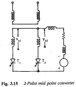
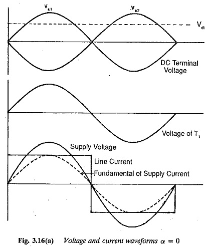
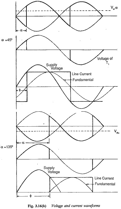
The branch which has a higher voltage with respect to the midpoint can be made to conduct by giving a firing pulse to the thyristor in that branch. The midpoint of the secondary serves as the return for the current. The thyristor T1 can be fired when υs1 is positive and T2 can be fired when υs2 is positive with respect to the midpoint. The thyristor conducts the load current when its voltage is positive, once it is turned ON. The output voltage and current waveforms, assuming a highly inductive load are given in Fig. 3.16. If a thyristor, say T1 is switched ON when the voltage is positive the current through the load builds up. T1 maintains conduction, depending upon the nature of the load, even in the period when υs1 is negative. At this stage υs2 becomes positive and thyristor T2 takes over if a firing pulse is given. Assuming instantaneous commutation, performance, equations of the converter can be derived. Assuming a turns ratio of unity for the transformer and neglecting the commutation reactances, the average voltage at the dc terminals of a Two pulse mid point converter can be derived as
![]()
where α is the firing angle of the converter. For firing delay angles in the range 0 to 90° the converter operates as a rectifier providing dc voltage at the load. Power transfer takes place from ac to dc. For angles in the range 90° to 180° (theoretically) the converter operates in the inverting mode. If there is a dc source on the dc side, dc power can be converted to ac. However, in practice a firing angle of 180° cannot be reached due to overlap and the finite amount of time taken by the thyristor to go to a blocking state.
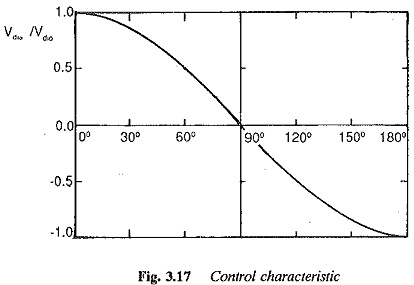
The average dc voltage is maximum at a firing angle of 0°, It decreases as the firing angle changes from 0 to 90°, and finally becomes zero when the firing angle is 90°. The voltage reverses its polarity for firing angles greater than 90° and increases with reversed polarity as a is increased beyond 90°. It reaches its maximum negative value at α = 180° (Fig. 3.17).
The average value of the thyristor current
![]()
The rms value of the thyristor current
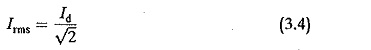
Using these values of voltages and currents the ratings of the converter trans-former can be obtained. The rating of the secondary winding is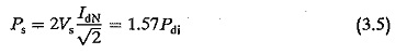
The design rating of the transformer is
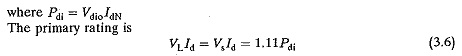
The design rating of transformer is
![]()
The increased rating of the transformers is due to the dc component of the current.
The peak forward or reverse voltages applied to the thyristors are
![]()
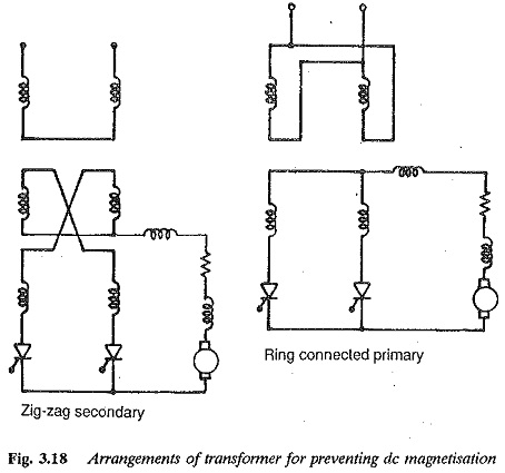
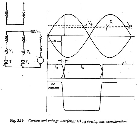
The premagnetisation of the transformer existing in the circuit of Fig. 3.15 can be avoided by the ring connection of the transformer shown in Fig. 3.18. Overlap the current through the load builds up when a thyristor is turned ON and the voltage across it is positive. Say, for example, T1 is fired when Vs1 is positive. T1 maintains its conduction till the next thyristor is fired at any instant during its positive voltage. Vs2 becomes positive when Vs1 becomes negative. Thyristor T2 is fired. The current transfer takes place from T1 to T2 The preceding discussion has assumed instantaneous commutation. But in practice, due to the leakage reactance of the transformer, and the line inductances and additional inductances of the circuit (to protect the thyristors from di/dt), the transfer of current is never instantaneous, but takes a definite amount of time. During commutation both the thyristors conduct. The current of the outgoing thyristor decreases and that of the incoming one increases. The process is complete when all the current has been transferred to the incoming thyristor. The angle of overlap is denoted by u. The voltage and current wave forms of the converter, taking overlap into consideration, are shown in Fig. 3.19.
The effect of overlap is to cause a kind of voltage drop at the output terminals. The average value of the dc voltage at the dc terminals of the converter is![]()
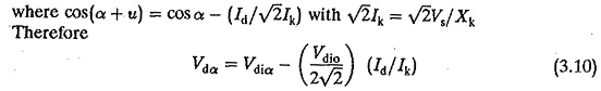
Therefore, as the converter is loaded there is a reduction in the terminal voltage. This reduction is called voltage regulation. Besides overlap, the drops in the thyristors and circuit resistances contribute to voltage regulation. During overlap the rate of change of current causes a drop in the inductive reactances in series with the thyristors, which is the main cause of voltage regulation.
The mean dc voltage of a Two pulse mid point converter is superimposed by a ripple voltage of twice the supply frequency. The ripple content is minimum at α = 0° and increases to a maximum at α = 90°. When α is increased further the ripple content decreases and falls to minimum when α = 180°.
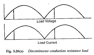
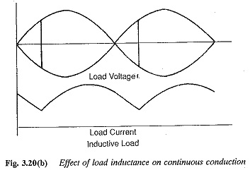
When the load is purely resistive, the current in it becomes discontinuous. To explain this, note that the current is in phase with the voltage. When the load voltage falls to zero and the thyristor is reverse biased, conduction ceases. When the load has sufficient inductance one thyristor conducts for 180° and the other thyristor takes over before the load current falls to zero. Thus, conduction is made continuous. The load current becomes pure dc if the load has infinite inductance.
The mean value of the dc output voltage would be different for the cases of continuous and discontinuous conduction for the same firing angle being less for the former case. This is mainly because negative excursions of the voltage are possible across the load in the case of continuous conduction, as the load current is maintained even after the voltage has become negative. The back emf load on a converter is prone to discontinuous conduction. A resistive load inherently has discontinuous conduction. These cases are depicted in Fig. 3.20.
The performance of a converter is characterised by the superimposed ripple content of ac voltage on the mean dc voltage. The effective value of the rth harmonic referred to Vdi is neglecting the overlap. When the effect of the overlap is taken into consideration, the effective value of the rth harmonic referred to Vdi would be
![]()
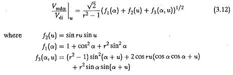
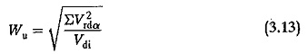
The ripple content can be easily calculated as the ratio of the effective value of superimposed ac voltage to ideal dc voltage
For a Two pulse mid point converter the ripple content is 48.2% for α = 0° and 111.1% for α = 90°.
A smoothing inductance is necessary in the load circuit. This inductance serves two purposes:
- to smooth the ripple content of output current
- to make conduction continuous in the load or to minimise the possibility of discontinuous conduction.
The value of Ld is normally determined such as to avoid discontinuous conduction rather than to smoothen out the ripple content. The layout of the smoothing inductance is rather large. The smoothing inductance required in the load circuit is
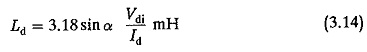
where
Vdi average value of dc voltage
α firing angle at which the smoothing is required
Id is the dc current at which the conduction must be continuous
The performance of a converter is also characterised by harmonic currents on the ac side. The harmonic components present on the ac side do not contribute to any power transfer. On the other hand, they cause undesirable effects in converter operation and also reduce the power factor markedly. They may cause resonance effects due to the line inductance and capacitance. When overlap is neglected, the rms value of the harmonic current referred to the fundamental is
For a single phase![]()
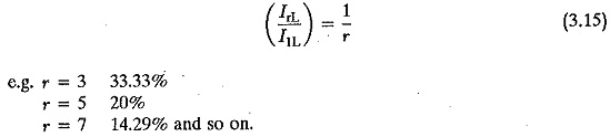
The effective value of the line current expressed as the ratio of the fundamental
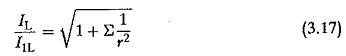
For a Two pulse mid point converter this ratio is 111.1%. This distortion of the input ac current is also seen by examining the fundamental content of the input current. The ratio of the fundamental component to the total rms current, g = I1L/IL. For a Two pulse mid point converter
![]()
When the overlap μ is taken into consideration
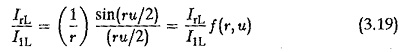
The effect of overlap is to reduce the distortion on the ac side and decrease the rms value of a harmonic.
The reactive power required by a converter is also a significant factor in evaluating its performance. The fundamental displacement factor is the phase difference between the voltage and the fundamental of input current. From the waveforms of Fig. 3.16 the displacement factor is cos α. The total power factor on the input side is somewhat less than the displacement factor. It can be shown that the total power factor is given by
![]()
For a Two pulse mid point converter, g = 0.9. The harmonics therefore effectively decrease the pf even though they do not contribute to power transfer.
The reactive power required by a converter is due to the phase control employed, as well as commutation. Unlike the active power which is decided by the fundamental only, the control reactive power is decided by the harmonics also. The fundamental displacement factor is the cosine of the control angle. When commutation is considered there is a certain overlap angle, because of which the current waveform shifts further to the right, increasing the angle of lag of the current. The overlap angle depends upon the firing angle. The reactive power required because of phase control is VdiVd sin α and it increases as the firing angle increases, or the pf becomes poor. The reactive power due to commutation overlap is
![]()
where uo is the overlap angle at α = 0°. It can be shown that the reactive power required by the converter at a given firing angle α is
![]()
The fundamental displacement factor, taking overlap into consideration is approximately cos(α + u/2) or cos(α + 2u/3) depending upon 60 < α < 90° or 0 < α < 30°.