Tropospheric Scatter Propagation:
Tropospheric Scatter Propagation is a means of beyond-the-horizon propagation for UHF signals. Tropospheric Scatter Propagation uses certain properties of the troposphere, the nearest portion of the atmosphere (within about 15 km of the ground).
Properties of Tropospheric Scatter Propagation:
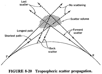
As shown in Figure 8-20, two directional antennas are pointed so that their beams intersect midway between them, above the horizon. If one of these is a UHF transmitting antenna, and the other a UHF receiving one, sufficient radio energy will be directed toward the receiving antenna to make this a useful communication system. The reasons for the scattering are not fully understood, but there are two theories. One suggests reflections from “blobs” in the atmosphere, similar to the scattering of a searchlight beam by dust particles, and the other postulates reflection from atmospheric layers. Either way, this is a permanent state of affairs, not a sporadic phenomenon.
The best frequencies, which are also the most often used, are centered on 900, 2000 and 5000 MHz. Even here the actual proportion of forward scatter to signals incident on the scatter volume is very tiny between 60 and 90 dB, or one-millionth to one-billionth of the incident power. High transmitting powers are obviously needed.
Practical considerations:
Although forward scatter is subject to fading, with little signal scattered forward, it nevertheless forms a very reliable method of over-the-horizon communication. It is not affected by the abnormal phenomena that afflict HF sky-wave propagation. Accordingly, this method of propagation is often used to provide long-distance telephone and other communications links, as an alternative to microwave links or coaxial cables over rough or inaccessible terrain. Path links are typically 300 to 500 km long.
Tropospheric scatter propagation is subject to two forms of fading. The first is fast, occurring several times per minute at its worst, with maximum signal strength variations in excess of 20 dB. It is often called Rayleigh fading and is caused by multi path propagation.
As Figure 8-20 shows, scattering is from a volume, not a point, so that several paths for propagation exist within the scatter volume. The second form of fading is very much slower and is caused by variations in atmospheric conditions along the path.
It has been found in practice that the best results are obtained from Tropospheric Scatter Propagation if antennas are elevated and then directed down toward the horizon. Also, because of the fading problems, diversity systems are invariably employed, with space diversity more common than frequency diversity. Quadruple diversity systems are generally employed, with two antennas at either end of the link (all used for transmission and reception) separated by distances somewhat in excess of 30 wavelengths.