Transistor RF Amplifier Circuit:
A radio receiver always has an RF section, which is a tunable circuit connected to the antenna terminals. It is there to select the wanted frequency and reject some of the unwanted frequencies. However, such a receiver need not have an Transistor RF Amplifier Circuit following this tuned circuit. If there is an amplifier its output is fed to the mixer at whose input another tunable circuit is present. In many instances, however, the tuned circuit connected to the antenna is the actual input circuit of the mixer. The receiver is then said to have no RF amplifier.
Reasons for use and functions of RF amplifier:
The receiver having an RF stage is undoubtedly superior in performance to the receiver without one, all else being equal. On the other hand, there are some instances in which an Transistor RF Amplifier Circuit is uneconomical, i.e., where its inclusion would increase the cost of the receiver significantly while improving performance only marginally. The best example of this kind of receiver is a domestic one used in a high-signal-strength area, such as the metropolitan area of any large city.
The advantages of having an Transistor RF Amplifier Circuit are as follows:
- Greater gain, i.e., better sensitivity
- Improved image-frequency rejection
- Improved signal-to-noise ratio
- Improved rejection of adjacent unwanted signals, i.e., better selectivity
- Better coupling of the receiver to the antenna (important at VHF and above)
- Prevention of spurious frequencies from entering the mixer and heterodyning there to produce an interfering frequency equal to the IF from the desired signal
- Prevention of re radiation of the local oscillator through the antenna of the receiver (relatively rare)
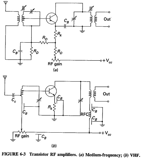
The single-tuned, transformer-coupled amplifier is most commonly employed for RF amplification, as illustrated in Figure 6-3. Both diagrams in the figure are seen to have an RF gain control, which is very rare with domestic receivers but quite common in communications receivers. The medium-frequency amplifier of Figure 6-3a is quite straightforward, but the VHF amplifier of Figure 6-3b contains a number of refinements. Feed through capacitors are used as bypass capacitors and, in conjunction with the RF choke, to decouple the output from the Vcc. As indicated in Figure 6-3b, one of the electrodes of a feed through capacitor is the wire running through it. This is surrounded by the dielectric, and around that is the grounded outer electrode. This arrangement minimizes stray inductance in series with the bypass capacitor. Feed through capacitors are almost invariably provided for bypassing at VHF and often have a value of 1000 pF. A single-tuned circuit is used at the input and is coupled to the antenna by means of a trimmer (the latter being manually adjustable for matching to different antennas). Such coupling is used here because of the high frequencies involved. In practice Transistor RF Amplifier Circuit have the input and output tuning capacitors ganged to each other and to the one tuning the local oscillator.
Sensitivity:
The sensitivity of a radio receiver is its ability to amplify weak signals. It is often defined in terms of the voltage that must be applied to the receiver input terminals to give a standard output power, measured at the output terminals. For AM broadcast receivers, several of the relevant quantities have been standardized. Thus 30 percent modulation by a 400-Hz sine wave is used, and the signal is applied to the receiver through a standard coupling network known as a dummy antenna. The standard output is 50 milliwatts (50 mW), and for all types of receivers the loudspeaker is replaced by a load resistance of equal value.
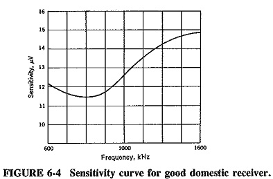
Sensitivity is often expressed in micro volts or in decibels below 1 V and measured at three points along the tuning range when a production receiver is lined up. It is seen from the sensitivity curve in Figure 6-4 that sensitivity varies over the tuning band. At 1000 kHz, this particular receiver has a sensitivity of 12.7 μV, or – 98 dBV (dB below 1 V). Sometimes the sensitivity definition is extended, and the manufacturer of this receiver may quote it to be, not merely 12.7 μW, but “12.7 μW for a signal-to-noise ratio of 20 dB in the output of the receiver.”
For professional receivers, there is a tendency to quote the sensitivity in terms of signal power required to produce a minimum acceptable output signal with a minimum acceptable signal-to-noise ratio. The measurements are made under the conditions described, and the minimum input power is quoted in dB below 1 mW or dBm. Under the heading of “sensitivity” in the specifications of a receiver, a manufacturer might quote, “a – 85-dBm 1-MHz signal, 30 percent modulated with a 400-Hz sine wave will, when applied to the input terminals of this receiver through a dummy antenna, produce an output of at least 50 mW with a signal-to-noise ratio not less than 20 dB in the output.”
The most important factors determining the sensitivity of a superheterodyne receiver are the gain of the IF amplifier(s) and that of the Transistor RF Amplifier Circuit, if there is one. It is obvious that the noise figure plays an important part. Figure 6-4 shows the sensitivity plot of a rather good domestic or car radio. Portable and other small receivers used only for the broadcast band might have a sensitivity in the vicinity of 150 μV, whereas the sensitivity of quality communications receivers may be better than 1 μV in the HF band.
Selectivity:
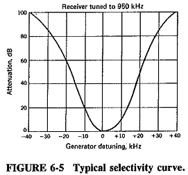
The selectivity of a receiver is its ability to reject unwanted signals. It is expressed as a curve, such as the one of Figure 6-5, which shows the attenuation that the receiver offers to signals at frequencies near to the one to which it is tuned. Selectivity is measured at the end of a sensitivity test with conditions the same as for sensitivity, except that now the frequency of the generator is varied to either side of the frequency to which the receiver is tuned. The output of the receiver naturally falls, since the input frequency is now incorrect. The input voltage must be increased until the output is the same as it was originally. The ratio of the voltage required of resonance to the voltage required when the generator is tuned to the receiver’s frequency is calculated at a number of points and then plotted in decibels to give a curve, of which the one in Figure 6-5 is representative. Looking at the curve, we see that at 20 kHz below the receiver tuned frequency, an interfering signal would have to be 60 dB greater than the wanted signal to come out with the same amplitude.
Selectivity varies with receiving frequency if ordinary tuned circuits are used in the IF section, and becomes somewhat worse when the receiving frequency is raised. In general, it is determined by the response of the IF section, with the mixer and RF amplifier input circuits playing a small but significant part. It should be noted that it is selectivity that determines the adjacent-channel rejection of a receiver.
Image frequency and its rejection:
In a standard broadcast receiver (and, in fact, in the vast majority of all receivers made) the local oscillator frequency is made higher than the incoming signal frequency for reasons that will become apparent. It is made equal at all times to the signal frequency plus the intermediate frequency. Thus f0 = fs+fi, or fs = fo-fi, no matter what the signal frequency may be. When fs and fo are mixed, the difference frequency, which is one of the by-products, is equal to fi. As such, it is the only one passed and amplified by the IF stage.
If a fsi frequency manages to reach the mixer, such that fsi = fo + fi, that is, fsi = fs + 2fi, then this frequency will also produce fi when mixed with fo. The relationship of these frequencies is shown in Figure 3-2, though in a different context. Unfortunately, this spurious intermediate-frequency signal will also be amplified by the IF stage and will therefore provide interference. This has the effect of two stations being received simultaneously and is naturally undesirable. The term fsi is called the image frequency and is defined as the signal frequency plus twice the intermediate frequency.
Reiterating, we have
![]()
The rejection of an image frequency by a single-tuned circuit, i.e., the ratio of the gain at the signal frequency to the gain at the image frequency, is given by
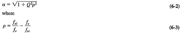
Q = loaded Q of tuned circuit
If the receiver has an RF stage, then there are two tuned circuits, both tuned to fs. The rejection of each will be calculated by the same formula, and the total rejection will be the product of the two. Whatever applies to gain calculations applies also to those involving rejection.
Image rejection depends on the front-end selectivity of the receiver and must be achieved before the IF stage. Once the spurious frequency enters the first IF amplifier, it becomes impossible to remove it from the wanted signal. It can be seen that if fsi/fs is large, as it is in the AM broadcast band, the use of an RF stage is not essential for good image-frequency rejection, but it does become necessary above about 3 MHz.
Adjacent channel selectivity (Double spotting):
This is a well-known phenomenon, which manifests itself by the picking up of the same shortwave station at two nearby points on the receiver dial. It is caused by poor front-end selectivity, i.e., inadequate image-frequency rejection. That is to say, the front end of the receiver does not select different adjacent signals very well, but the IF stage takes care of eliminating almost all of them. This being the case, it is obvious that the precise tuning of the local oscillator is what determines which signal will be amplified by the IF stage. Within broad limits, the setting of the tuned circuit at the input of the mixer is far less important (it being assumed that there is no Transistor RF Amplifier Circuit in a receiver which badly suffers from double spotting). Consider such a receiver at HF, having an IF of 455 kHz. If there is a strong station at 14.7 MHz, the receiver will naturally pick it up. When it does, the local oscillator frequency will be 15.155 MHz. The receiver will also pick up this strong station when it (the receiver) is tuned to 13.790 MHz. When the receiver is tuned to the second frequency, its local oscillator will be adjusted to 14.245 MHz. Since this is exactly 455 kHz below the frequency of the strong station, the two signals will produce 455 kHz when they are mixed, and the IF amplifier will not reject this signal. If there had been an Transistor RF Amplifier Circuit, the 14.7-MHz signal might have been rejected before reaching the mixer, but without an RF amplifier this receiver cannot adequately reject 14.7 MHz when it is tuned to 13.79 MHz.
Lack of selectivity is harmful because a weak station may be masked by the reception of a nearby strong station at the spurious point on the dial. As a matter of interest, double spotting may be used to calculate the intermediate frequency of an unknown receiver, since the spurious point on the dial is precisely 2fi below the correct frequency. (As expected, an improvement in image-frequency rejection will produce a corresponding reduction in double spotting.)