Transformer Substation:
The majority of the sub-stations in the power system are concerned with the changing of voltage level of electric supply. These are known as Transformer Substation because transformer is the main component employed to change the voltage level. Depending upon the purpose served, Transformer Substation may be classified into :
-
Step-up sub-station
-
Primary grid sub-station
-
Secondary sub-station
-
Distribution sub-station
Fig. 25.1 shows the block diagram of a typical electric supply system indicating the position of above types of sub-stations. It may be noted that it is not necessary that all electric supply schemes include all the stages shown in the figure. For example, in a certain supply scheme there may not be secondary sub-stations and in another case, the scheme may be so small that there are only distribution sub-stations.
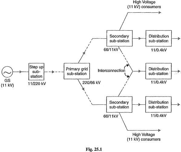
1. Step-up sub-station: The generation voltage (11 kV in this case) is stepped up to high voltage (220 kV) to affect economy in transmission of electric power. The sub-stations which accomplish this job are called step-up sub-stations. These are generally located in the power houses and are of outdoor type.
2. Primary grid sub-station: From the step-up sub-station, electric power at 220kV is transmitted by 3-phase, 3-wire overhead system to the outskirts of the city. Here, electric power is received by the primary grid sub-station which reduces the voltage level to 66 kV for secondary transmission. The primary grid sub-station, is generally of outdoor type.
3. Secondary sub-station: From the primary grid sub-station, electric power is transmitted at 66 kV by 3-phase, 3-wire system to various secondary sub-stations located at the strategic points in the city. At a secondary sub-station, the voltage is further stepped down to 11 kV. The 11 kV lines run along the important road sides of the city. It may be noted that big consumers (having demand more than 50 kW) are generally supplied power at 11 kV for further handling with their own sub-stations. The secondary sub-stations are also generally of outdoor type.
4. Distribution sub-station: The electric power from 11 kV lines is delivered to distribution sub-stations. These sub-stations are located near the consumers localities and step down the voltage to 400 V, 3-phase, 4-wire for supplying to the consumers. The voltage between any two phases is 400V and between any phase and neutral it is 230 V. The single phase residential lighting load is connected between any one phase and neutral whereas 3-phase, 400V motor load is connected across 3-phase lines directly. It may be worthwhile to mention here that majority of the distribution substations are of pole-mounted type.
Pole Mounted Substation:
It is a distribution sub-station placed overhead on a’ pole. It is the cheapest form of sub-station as it does not involve any building work. Fig 25.2 (i) shows the layout of pole-mounted sub-station whereas Fig. 25.2 (ii) shows the schematic connections. The transformer and other equipment are mounted on H-type pole (or 4-pole structure).
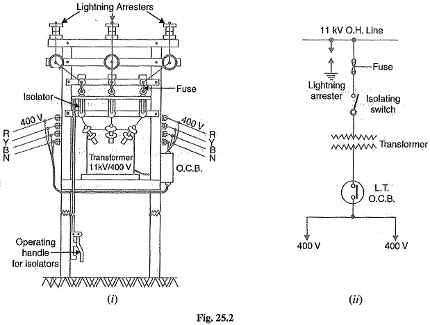
The 11 kV line is connected to the transformer (11kV / 400 V) through gang isolator and fuses. The lightning arresters are installed on the H.T. side to protect the sub-station from lightning strokes. The transformer steps down the voltage to 400V, 3-phase, 4-wire supply. The voltage between any two lines is 400V whereas the voltage betw,een any line and neutral is 230 V. The oil circuit breaker (O.C.B.) installed on the L.T. side automatically isolates the transformer from the consumers in the event of any fault. The pole-mounted sub-stations are generally used for transformer capacity upto 200 kVA. The following points may be noted about pole-mounted sub-stations :
- There should be periodical check-up of the dielectric strength of oil in the transformer and O.C.B.
- In case of repair of transformer or O.C.B., both gang isolator and O.C.B. should be shut off.
Underground Substation:
In thickly populated cities, there is scarcity of land as well as the prices of land are very high. This has led to the development of underground sub-station. In such sub-stations, the equipment is placed underground. Fig. 25.3 shows a typical underground sub-station.
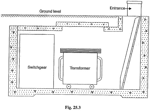
The design of underground sub-station requires more careful consideration than other types of sub-stations. While laying out an underground sub-station, the following points must be kept in view:
- The size of the station should be as minimum as possible.
- There should be reasonable access for both equipment and personnel.
- There should be provision for emergency lighting and protection against fire.
- There should be good ventilation.
- There should be provision for remote indication of excessive rise in temperature so that H.V. supply can be disconnected.
- The Transformer Substation, switches and fuses should be air cooled to avoid bringing oil into the premises.