Tirril Voltage Regulator:
In this type of Tirril Voltage Regulator, a fixed resistance is cut in and cut out of the exciter field circuit of the alternator. This is achieved by rapidly opening and closing a shunt circuit across the exciter rheostat. For this reason, it is also known as vibrating type voltage regulator.
Construction. Fig. 15.1 shows the essential parts of a Tirril voltage regulator. A rheostat R is provided in the exciter circuit and its value is set to give the required excitation. This rheostat is put in and out of the exciter circuit by the regulator, thus varying the exciter voltage to maintain the desired voltage of the alternator.
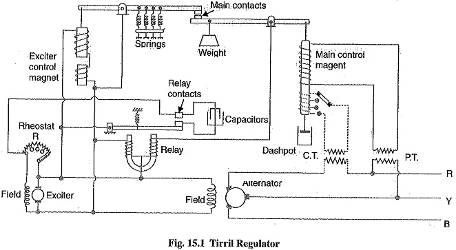
- Main contact: There are two levers at the top which carry the main contacts at the facing The left-hand lever is controlled by the exciter magnet whereas the right hand lever is controlled by an a.c. magnet known as main control magnet.
- Exciter magnet: This magnet is of the ordinary solenoid type and is connected across the exciter mains. Its exciting current is, therefore, proportional to the exciter voltage. The counter balancing force for the exciter magnet is provided by four coil springs.
- A.C. magnet: It is also of solenoid type and is energized from a.c. bus-bars. It carries series as well as shunt excitation. This magnet is so adjusted that with normal load and voltage at the alternator, the pulls of the two coils are equal and opposite, thus keeping the right-hand lever in the horizontal position,
- Differential relay: It essentially consists of a U-shaped relay magnet which operates the relay contacts. The relay magnet has two identical windings wound differentially on both the limbs. These windings are connected across the exciter mains—the left hand one permanently while the right hand one has its circuit completed only when the main contacts are closed. The relay contacts are arranged to shunt the exciter-field rheostat A capacitor is provided across the relay contacts to reduce the sparking at the time the relay contacts are opened.
Operation: The two control magnets (i.e. exciter magnet and a.c. magnet) are so adjusted that with normal load and voltage at the alternator, their pulls are equal, thus keeping the main contacts open. In this position of main contacts, the relay magnet remains energized and pulls down the armature carrying one relay contact. Consequently, relay contacts remain open and the exciter field rheostat is in the field circuit.
When the load on the alternator increases, its terminal voltage tends to fall. This causes the series excitation to predominate and the a.c. magnet pulls down the right-hand lever to close the main contacts. Consequently, the relay magnet is de-energised and releases the armature carrying the relay contact. The relay contacts are closed and the rheostat R in the field circuit is short circuited. This increases the exciter-voltage and hence the excitation of the alternator. The increased excitation causes the alternator voltage to rise quickly. At the same time, the excitation of the exciter magnet is increased due to the increase in exciter voltage. Therefore, the left-hand lever is pulled down, opening the main contacts, energizing the relay magnet and putting the rheostat R again in the field circuit before the alternator voltage has time to increase too far. The reverse would happen should the load on the alternator decrease.
It is worthwhile to mention here that:exciter voltage is controlled by the rapid opening and closing of the relay contacts. As the regulator is worked on the overshooting the mark principle, therefor; the terminal voltage does not remain absolutely constant but oscillates between the maximum and minimum values. In fact, the regulator is so quick acting that voltage variations never exceed ± 1%.