Time Graded Overcurrent Protection:
In this scheme of Time Graded Overcurrent Protection, time discrimination is incorporated. In other words, the time setting of relays is so graded that in the event of fault, the smallest possible part of the system is isolated. We shall discuss a few important cases.
1. Radial feeder: The main characteristic of a radial system is that power can flow only in one direction, from generator or supply end to the load. It has the disadvantage that continuity of supply cannot be maintained at the receiving end in the event of fault. Time Graded Overcurrent Protection protection of a radial feeder can be achieved by using
- Definite time relays and
- Inverse time relays.
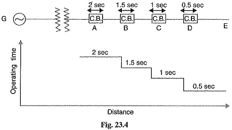
(i) Using definite time relays: Fig 23.4 shows the overcurrent protection of a radial feeder by definite time relays. The time of operation of each relay is fixed and is independent of the operating current. Thus relay D has an operating time of 0.5 second while for other relays, time delay is successively increased by 0.5 second. If a fault occurs in the section DE, it will be cleared in 0.5 second by the relay and circuit breaker at D because all other relays have higher operating time. In this way only section DE of the system will be isolated. If the relay at D fails to trip, the relay at C will operate after a time delay of 0.5 second i.e. after 1 second from the occurrence of fault.
The disadvantage of this system is that if there are a number of feeders in series, the tripping time for faults near the supply end becomes high (2 seconds in this case). However, in most cases, it is necessary to limit the maximum tripping time to 2 seconds. This disadvantage can be overcome to a reasonable extent by using inverse-time relays.
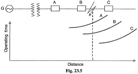
(ii) Using inverse lime relays: Fig 23.5 shows overcurrent protection of a radial feeder using inverse time relays in which operating time is inversely proportional this arrangement, the farther the circuit breaker from the generating operating time.
The three relays at A, B and C are assumed to have inverse-time characteristics. A fault in section BC will give relay times which will allow breaker at B to trip out before the breaker at A.
2. Parallel feeders: Where continuity of supply is particularly necessary, two parallel feeders may be installed. If a fault occurs on one feeder, it can be disconnected from the system and continuity of supply can be maintained from the other feeder. The parallel feeders cannot be protected by non-directional overcurrent relays only. It is necessary to use directional relays also and to grade the time setting of relays for selective trippings.
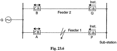
Fig. 23.6 shows the system where two feeders are connected in parallel between the generating station and the sub-station. The protection of this system requires that
- each feeder has a non-directional overcurrent relay at the generator end. These relays should have inverse-time characteristic.
- each feeder has a reverse power or directional relay at the sub-station end. These relays should be instantaneous type and operate only when power flows in the reverse direction e. in the direction of arrow at P and Q.
Suppose an earth fault occurs on feeder 1 as shown in Fig. 23.6. It is desired that only circuit breakers at A and P should open to clear the fault whereas feeder 2 should remain intact to maintain the continuity of supply. In fact, the above arrangement accomplishes this job. The shown fault is fed via two routes, viz.
- Directly from feeder 1 via the relay A
- From feeder 2 via B, Q, sub-station and P
Therefore, power flow in relay Q will be in normal direction but is reversed in the relay P. This causes the, opening of circuit breaker at P. Also the relay A will operate while relay B remains inoperative. It is because these relays have inverse-time characteristics and current flowing in relay A is in excess of that flowing in relay B. In this way only the faulty feeder is isolated.
3. Ring main system: In this system, various power stations or sub-stations are interconnected by alternate routes, thus forming a closed ring. In case of damage to any section of the ring, that section may be disconnected for repairs, and power will be supplied from both ends of the ring, thereby maintaining continuity of supply.
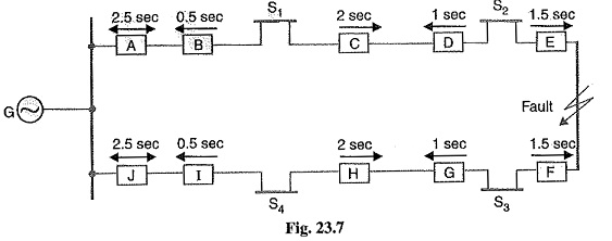
Fig. 23.7 shows the single line diagram of a typical ring main system consisting of one generator G supplying four sub-stations S1, S2, S3 and S4. In this arrangement, power can flow in both directions under fault conditions. Therefore, it is necessary to grade in both directions round the ring and also to use directional relays. In order that only faulty section of the ring is isolated under fault conditions, the types of relays and their time settings should be as follows :
- The two lines leaving the generating station should be equipped with non-directional overcurrent relays (relays at A and J in this case).
- At each sub-station, reverse power or directional relays should be placed in both incoming and outgoing lines (relays at B, C, D, E, F, G, H and I in this case).
- There should be proper relative time-setting of the relays. As an example, going round the loop G S1 S2 S3 S4 G ; the outgoing relays (viz at A, C, E, G and I) are set with decreasing time limits e.g.
![]()
Similarly, going round the loop in the opposite direction (i.e. along G S1 S2 S3 S4 G), the outgoing relays (J, H, F, D and B) are also set with a decreasing time limit e.g.
![]()
Suppose a short circuit occurs at the point as shown in Fig. 23.7. In order to ensure selectivity, it is desired that only circuit breakers at E and F should open to clear the fault whereas other sections of the ring should be intact to maintain continuity of supply. In fact, the above arrangement accomplishes this job. The power will be fed to the fault via two routes viz (i) from G around S1 and S2 and (ii) from G around S4 and S3. It is clear that relays at A, B, C and D as well as J, I, H and G will not trip. Therefore, only relays at E and F will operate before any other relay operates because of their lower time-setting.