Time Division Multiplexing(TDM):
Time Division Multiplexing – Any pulse modulation scheme involves translating the audio, or modulating signal into a series of encoded pulses, sending these pulses over a transmission medium and reverting the pulses back to an analog signal. Regardless of the encoding used, a PAM signal is always obtained initially.
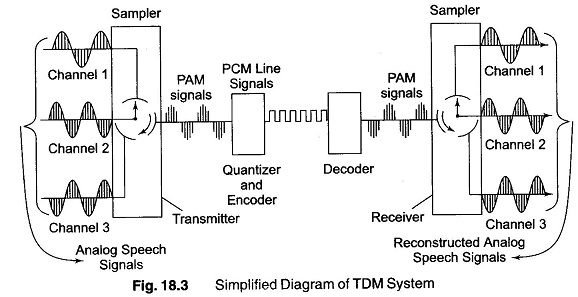
The audio signal is first sampled at a sufficiently high rate in order to minimise distortion. By keeping the samples short in comparison to the time intervals between them, many different channels can be interleaved in one sampling period. This process, as performed by a commutator, is illustrated in Fig. 18.3. It is commonly called Time Division Multiplexing (TDM).
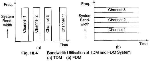
TDM allows each channel the full band width of the transmission medium whenever its signal is transmitted, although each channel is not continuously on the system. This is in contrast to Frequency Division Multiplexing (FDM), in which each channel is continuously on the system but allowed only a limited portion of the system band width. This is clearly illustrated in Fig. 18.4.
After a PAM signal is obtained, it can be transmitted directly or quantized and encoded to provide improved noise immunity. The latter is more commonly done.
An example of a 4 channel electronic sampling system is shown in Fig. 18.5. This system employs 2 F/Fs and MOS p-channel enhancement transistors as switches.
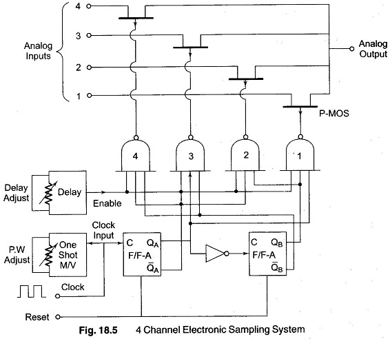
When the gate to the MOS p-transistor becomes negative, the p-channels act as a low impedance circuit, with a resistance of about 200 Ω.
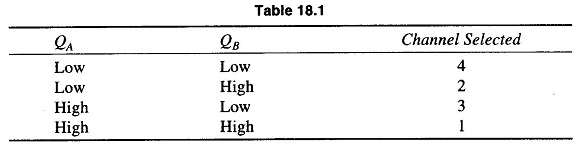
F/Fs A and B convert the serial clock input to binary parallel output. The four NAND gates decode this to sequentially drive the switches. When all the inputs to a NAND gate go high, the output goes low, thus causing the attached transistor to act as a low resistance path.
In order to establish a variable sampling aperture, the clock pulse is fed to a monostable multivibrator with pulse width adjusting control. This establishes the aperture time. A delay circuit then moves the sampling pulses such that the sampling occurs some time away from the gates switching edge.
Table 18.1 gives the F/F conditions for the channel selector.