Testing of Semiconductor Diode:
There are Several methods are available for Testing of Semiconductor Diode, namely,
Ohmmeter Tests:
One of the simplest and quickest tests can be made using an ohmmeter to measure the forward and reverse resistance of a diode, [see Fig. 222(a)]. The diode should offer a low resistance when forward biased, and a high resistance when reverse biased. A diode is short-circuited when it displays a low resistance for both forward and reverse bias. If a high resistance is measured with both bias polarities, the device is open-circuited. Usually, the actual indicated high resistance is approximately half the selected ohmmeter range.
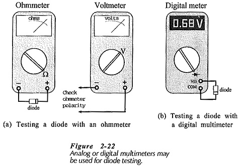
Obviously, the ohmmeter test will identify the anode and cathode of a diode, if there is doubt about the diode terminals. However, it is very important to note that when some multi function instruments are used as ohmmeters, the voltage polarity at the terminals may not be the same as the polarity marked on the instrument. A voltmeter should be used, as illustrated in Fig. 2-22(a), to check the ohmmeter terminal polarity.
Use of a Digital Meter:
Many portable multi function digital instruments have a Testing of Semiconductor Diode facility which displays the diode forward voltage when the terminals are connected positive to the anode, negative to the cathode (Fig. 2-22(b)]. When reverse connected, a functioning diode produces an 0L display. If an 0L display occurs with both forward and reverse connections, the diode is open-circuited. When the display is 000, the device is short-circuited.
Diode Characteristics Plotting:
The forward characteristics of a Testing of Semiconductor Diode can be obtained by use of the circuit illustrated in Fig. 2-23(a). The diode voltage is set at a series of convenient levels, and the corresponding current levels are measured and recorded. The characteristics are then plotted from the table of quantities obtained in this way. The reverse characteristics can be obtained in the same way, except that a very sensitive micro ammeter is required to measure the diode reverse current, [Fig. 2-23(b)). The micro ammeter must be connected directly in series with the diode, as shown; otherwise the voltmeter current may introduce a serious error.
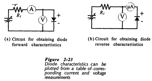
Figure 2-24 shows a method of using an XY recorder for drawing the forward characteristics of a diode. The resistor voltage (VR1) is directly proportional to the diode forward current (IF). So, VR1 is applied to the vertical input terminals of the XY recorder, as illustrated. The diode forward voltage (VF) goes to the horizontal input terminals. When the power supply voltage is slowly increased from zero, the diode forward characteristic is traced out by the pen on the KY recorder.
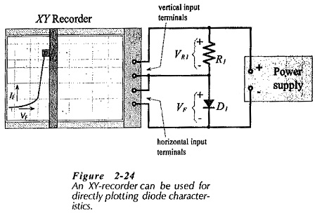
If R1 in Fig. 2-24 is a 1 kΩ resistor, there is a 1 V drop across R1 for every 1 mA of diode current. Therefore, with the vertical scale of the XY recorder set to 1 V/cm, the (vertical) current co-ordinate of the graph is 1 mA/cm. A convenient scale for the (horizontal) voltage co-ordinate is 0.1 V/cm. Testing of Semiconductor Diode can also be investigated by means of a curve tracer which displays the device characteristics on oscilloscope-type screen.