Temperature Controls using an Analog Electronic Controller:
A Temperature Controls scheme using an Analog Electronic Controller of Fig. 21.14 is as shown in Fig. 21.16.
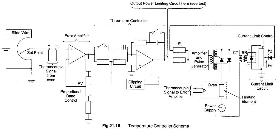
The temperature setting, derived from a slide wire, is compared with the signal from a thermocouple situated in the oven being heated. The difference between these two voltages is amplified in an error amplifier whose gain can be adjusted by means of potentiometer Rv, this potentiometer provides a means of modifying the proportional bandwidth of the controller.
The output voltage from this controller is applied to the input of a pulse generator which controls the delay angle of the pulses applied to the gate electrodes of the thyristor which regulate the current in the heating element. As the temperature of the oven rises, the gate pulses are phased back so that the oven power is reduced to a value which maintains the desired temperature.
To prevent excess current flowing in the thyristor or the heating element, electronic overcurrent protection is provided by the controller as follows. The ac current in the load is measured by means of a current transformer CT, and this current is converted into a direct voltage by means of the bridge rectifier BR and a potentiometer. Under normal operating conditions the voltage Vx at the wiper of the potentiometer is less than the breakdown voltage Vz of the zener diode, and no current flows through the zener diode. When excess current flows in the load, Vx exceeds Vz. and current flows through the zener diode and into resistor RL. The direction of this current is such that it causes the thyristor gate pulses to be phase backed to reduce the current flowing in the load to a safe value. The current limit setting is controlled by means of potentiometer wiper.