Switchgear Components in Circuit Breakers:
The following are some important components common to Switchgear Components in Circuit Breakers :
- Bushings
- Circuit breaker contacts
- Instrument transformers
- Bus-bars and conductors
1. Bushings: When a high voltage conductor passes through a metal sheet or frame which is at earth potential, the necessary insulation is provided in the form of bushing.
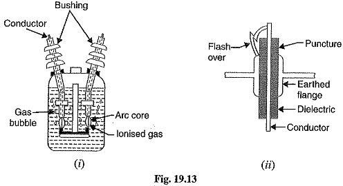
The Primary function of the bushing is to prevent electrical breakdown between the enclosed conductor and the surrounding earthed metal work. Fig. 19.13 (i) shows the use of bushing for a plain-break oil circuit breaker. The high voltage conductor passes through the bushing made of some insulating material (e.g., porcelain, steatite). Although there are several types of bushing (e.g., condenser type, oil filled etc.), they perform the same function of insulating the conductor from earthed tank.
The failure of the bushing can occur in two ways. Firstly, the beakdown may be caused by puncture i.e., dielectric failure of the insulating material of the bushing. Secondly, the breakdown may occur in the form of a flash-over between the exposed conductor at either end of the bushing and the earthed metal. Fig. 19.13 (ii) illustrates these two possibilities. The bushings are so designed that flash-over takes place before they get punctured. It is because the puncture generally renders the bushing insulation unserviceable and incapable of withstanding the normal voltage. On the other hand, a flash-over may result in comparatively harmless burning of the surface of the bushing which can then continue to give adequate service pending replacement.
2. Circuit breaker contacts: The circuit breaker contacts are required to carry normal as well as short-circuit current. In carrying the normal current, it is desirable that the temperature should not rise above the specified limits and that there should be low voltage drop at the point of contact. In carrying breaking and making short-circuit currents, the chief effects to be dealt with are melting and vaporization by the heat of the arc and those due to electromagnetic forces. Therefore, the design of contacts is of considerable importance for satisfactory operation of the circuit breakers. There are three types of circuit breaker contacts viz.
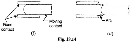
(a) Tulip type contacts: Fig. 19.14 (i) shows the Tulip type contact. It consists, of moving contact which moves inside the fixed contacts. At contact separation, the arc is generally established between the tips of the fixed contacts and the tip of the moving contact as shown in Fig. 19.14 (ii). The advantage of this type of contact is that arcing is confined to the regions which are not in contact in the fully engaged position.
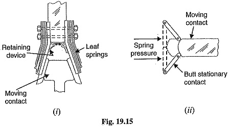
(b) Finger and wedge contacts: Fig. 19.15 (i) shows the finger and wedge type contact. This type of contact is largely used for low-voltage oil circuit breakers owing to the general unsuitability for use with arc control devices.
(c) Butt contacts: Fig. 19.15 (ii) shows the butt type contact and is formed by the springs and the moving contact. It possesses two advantages. Firstly, spring pressure is available to assist contact separation. This is useful in single-break oil circuit breakers and air-blast circuit breakers where relatively small “loop” forces are available to assist in opening. Secondly, there is no grip force so that this type of contact is especially suitable for higher short-circuit rating.
3. Instrument transformers: In a modern power system, the circuits operate at very high voltages and carry current of thousands of amperes. The measuring instruments and protective devices cannot work satisfactorily if mounted directly on the power lines. This difficulty is overcome by installing instrument transformers on the power lines. The function of these instrument transformers is to transform voltages or currents in the power lines to values which are convenient for the operation of measuring instruments and relays. There are two types of instrument transformers viz.
- Current transformer (C.T.)
- Potential transformer (P.T.)
The primary of current transformer is connected in the power line. The secondary winding provides for the instruments and relays a current which is a constant fraction of the current in the line.
Similarly, a potential transformer is connected with its primary in the power line. The secondary provides for the instruments and relays a voltage which is a known fraction of the line voltage.
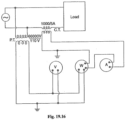
Fig. 19.16 shows the use of instrument transformers. The potential transformer rated 66,000/ 110V provides a voltage supply for the potential coils of voltmeter and wattmeter. The current transformer rated 1000/5 A supplies current to the current coils of wattmeter and ammeter. The use of instrument transformers permits the following advantages :
- They isolate the measuring instruments and relays from high-voltage power circuits.
- The leads in the secondary circuits carry relatively small voltages and currents. This permits to use wires of smaller size with minimum insulation.
4. Bus-bars and conductors: The current carrying members in a circuit breaker consist of fixed and moving contacts and the conductors connecting these to the points external to the breaker. If the Switchgear Components in Circuit Breakers is of outdoor type, these connections are connected directly to the overhead lines. In case of indoor Switchgear Components in Circuit Breakers, the incoming conductors to the circuit breaker are connected to the bus-bars.