Submarine Cables:
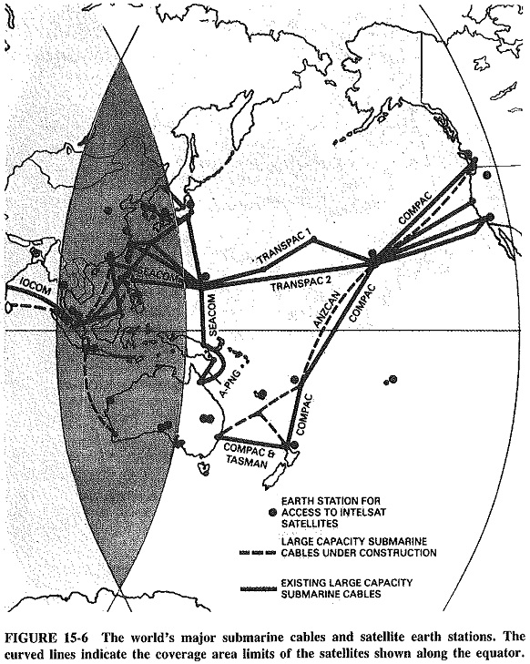
Submarine cables use principles very much like those of coaxial cables. Thus they are coaxial, have repeaters and equalizers and have dc power fed to them, with opposite polarities fed from opposite ends to reduce insulation problems. However, Submarine Cables use a single coaxial tube for both directions of transmission, with frequency techniques similar to those of microwave links to separate the two directions. The extent to which cables have spread out around the world, since TAT-1 in 1956, is shown in Figure 15-6.
Cables such as the 48-circuit TAT-1 and the 80-circuit CANTAT-1 (1961) are often referred to as “first-generation” cables. They feature vacuum-tube repeaters, at intervals of 50 to 60 km. Second-generation cables, such as the SAT-1 (1968) cable from Portugal to South Africa, have up to 360 circuits, with vacuum-tube repeaters at 18-km intervals. Vacuum tubes were used as late as 1968 because of their proven reliability. Submerged cable or repeater repair is perfectly feasible, but is a complex and costly process. It involves sending cableships to the affected area and dragging the sea bottom for the cable, while the interrupted circuits are restored via another cable or a satellite (at no small cost). It can therefore be appreciated that reliability is the keynote, and vacuum tubes had certainly established a reputation for that in Submarine Cables systems.
However, increased bandwidths mean reduced repeater gains and increased cable losses, and so repeaters must be placed closer together. For long cable segments, this results in unduly high dc voltages required at the two ends to accommodate the 70-V drop per vacuum tube repeater. Thus the third- and subsequent-generation cables have used transistor repeaters exclusively, with voltage drops of only 12 V per repeater. The TASMAN cable (1974, 480 circuits from Australia to New Zealand) and the TAT-5 cable (1970, 845 circuits from the United States to Spain)
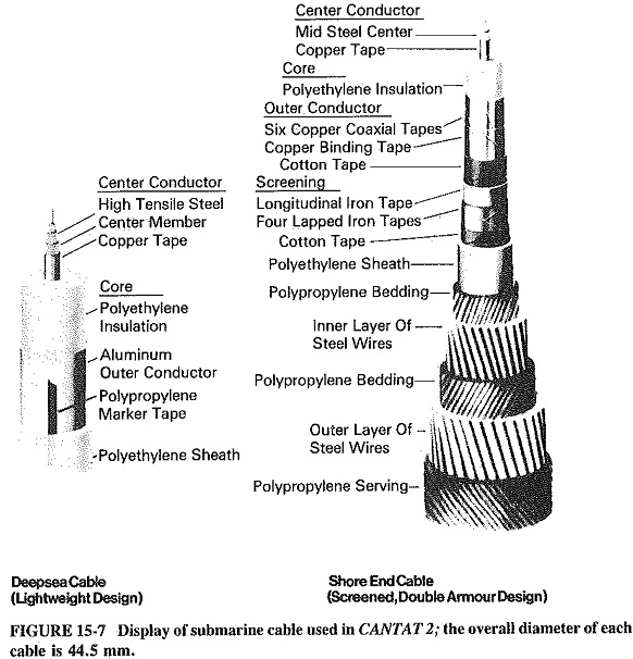
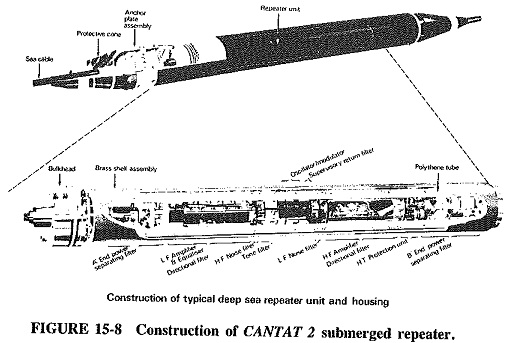
CANTAT 2 is typical of fourth-generation cables. It was laid in 1974 and provides 1840 circuits between Canada and Great Britain. Figure 15-7 shows the cable, both lightweight and armored, used in CANTAT 2, and a repeater from the system is shown in Figure 15-8. The repeaters are, of course, all solid-state, with separations of about 11 km in practice. This is a very successful design, first used in 1971 for a cable between Spain and the Canary Islands and subsequently employed in the Mediterranean (several cables), the Atlantic (COLUMBUS, southern segment of ATLANTIS, in 1982) and the Pacific (ANZCAN, 1984), as well as several shorter cables in Europe and southeast Asia.
Cable is laid by cableships operating from the two ends separately and sometimes simultaneously, moving at typical speeds of about 8 knots (about 15 km/h) the final splice is thus the midocean one. Lightweight cable is used for most of the length, including all deep sea portions. Sometimes, where great depths are involved, the cable is laid with sea parachutes, to slow its descent and therefore the rate of temperature change undergone by the cable and electronic components. The repeaters are rigid, and ingenious methods of bypassing shipboard sheaves have been developed. Armored cable is used for the shore ends as protection against trawlers, ships’ anchors and tidal movements. In well-known fishing areas, particularly if they are shallow, the technique of ploughing-in is used if the sea bottom permits. As the cable is paid out from the ship, a specially designed Submarine Cables, towed by a wire, cuts a 60-cm-deep trench for the cable to fall into; the trench is then covered. This was in fact done for the first 220 km of the CANTAT 2 cable off the Canadian continental shelf, except for the repeaters, which were too thick to be buried.
The CANTAT 2 repeaters, typical in this regard, are 25 cm in diameter and nearly 3 m long. Their function, as might be gathered, is simply to amplify. This must be done for both directions. The function of the power-separating and the directional filters in Figure 15-8 is to help in this regard. In the CANTAT 2 cable, the 23 supergroups are accommodated in the frequency band 312 to 6012 kHz in one direction, and 8000 to 13,700 kHz in the other direction. Inquisitive students who perform the appropriate calculations will realize that the above figures correspond to 3-kHz circuits and 80-circuit supergroups. It will be recalled that submarine cables are expensive, and 3-kHz voice circuits are often used. Supervisory tones and cable and system pilots are assigned various portions of the nearly 14-MHz spectrum, leaving 940 kHz for separation between the two directions; this is quite adequate in practice.
Reliability is the keynote of a Submarine Cables project. This point cannot be stressed enough. Whether it is the cable itself, repeaters, equalizers, cable station terminal equipment or power feed equipment, everything is engineered for a long life and slight, predictable aging. All cable and repeater welding is done by specially trained personnel, and all welds are checked by x-ray. The electronic components are assembled and tested under dustfree, laboratory conditions. All the components are used at well below their maximum ratings, and key components are duplicated. The performance of the system is monitored by the cableship during laying, and from the terminals for the rest of the cable life. Power feed arrangements are I complex, with main supplies rectified and regulated at the terminals and then used to float-charge the banks of batteries which feed dc/ac converters whose rectified output is actually fed to the cable at constant current. Duplicate batteries and standby diesel generators are provided, as are complicated interlock arrangements. All this is done to prevent the worst crime that can be perpetrated on a submarine cable: the sudden removal of the dc power feed.
The precautions as outlined are severe, but they have certainly paid off. The majority of the Submarine Cables that have been laid since 1956 are still operating, “delivering their circuits.” This is not to say that outages have never occurred. They
certainly have, but almost always through accidents rather than malfunctions. The most common causes of failure have been fouling by ships’ anchors or trawlers, with occasional turbidity currents (undersea avalanches caused by nearby earthquakes) also making a contribution. However, since satellite stations are now widespread, restoration of the affected portions of damaged cables is relatively straightforward. For example, if the SAT-1 cable fails between Ascension Island and South Africa, that portion of the cable can be restored by being sent via an INTELSAT Atlantic Ocean satellite. The cable then remains configured with one of its legs going via satellite until repairs are effected, so that most of the users suffer a minor interruption instead of a major outage. There are always contingency plans for the restoration of each leg of every cable.
Cables larger than the 14-MHz, 23-supergroup CANTAT 2 type are also available. They include a 43-supergroup French cable, a 45-supergroup Japanese cable, a 50.8-supergroup American cable and a 69-supergroup British cable (capable of providing 5520 telephone circuits). They are used for a number of high-density applications, but only the American cable is used in intercontinental systems, for example, TAT-6 and TAT-7. It is almost as though users were awaiting the advent of fiber optics.