Storage Oscilloscope (For VLF Signal):
Storage Oscilloscope – Storage targets can be distinguished from standard phosphor targets by their ability to retain a waveform pattern for a long time, independent of phosphor peristence. Two storage techniques are used in oscilloscope CRTs, mesh storage and phosphor storage.
A mesh-Storage Oscilloscope uses a dielectric material deposited on a storage mesh as the storage target. This mesh is placed between the deflection plates and the standard phosphor target in the CRT. The writing beam, which is the focused electron beam of the standard CRT, charges the dielectric material positively where hit. The storage target is then bombarded with low velocity electrons from a flood gun and the positively charged areas of the storage target allow these electrons to pass through to the standard phosphor target and thereby reproduce the stored image on the screen. Thus the mesh storage has both a storage target and a phosphor display target. The phosphor Storage Oscilloscope uses a thin layer of phosphor to serve both as the storage and the display element.
Mesh Storage:
It is used to display Very Low Frequencies (VLF) signals and finds many applications in mechanical and biomedical fields. The conventional scope has a display with a phosphor peristence ranging from a few micro seconds to a few seconds. The persistence can be increased to a few hours from a few seconds.
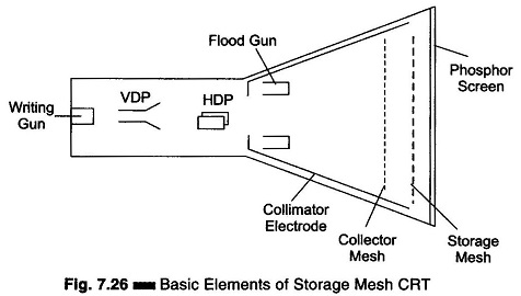
A mesh Storage Oscilloscope, shown in Fig. 7.26, contains a dielectric material deposited on a storage mesh, a collector mesh, flood guns and a collimator, in addition to all the elements of a standard CRT. The storage target, a thin deposition of a dielectric material such as Magnesium Fluoride on the storage mesh, makes use of a property known as secondary emission. The writing gun etches a positively charged pattern on the storage mesh or target by knocking off secondary emission electrons. Because of the excellent insulating property of the Magnesium Fluoride coating, this positively charged pattern remains exactly in the position where it is deposited. In order to make a pattern visible, a special electron gun, called the flood gun, is switched on (even after many hours).
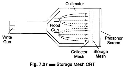
The electron paths are adjusted by the collimator electrode, which constitutes a low voltage electrostatic lens system (to focus the electron beam), as shown in Fig. 7.27. Most of the electrons are stopped and collected by the collector mesh. Only electrons near the stored positive charge are pulled to the storage target with sufficient force to hit the phosphor screen. The CRT will now display the signal and it will remain visible as long as the flood guns operate. To erase the pattern on the storage mesh, a negative voltage is applied to neutralize the stored positive charge.
Since the storage mesh makes use of secondary emission, between the first and second crossover more electrons are emitted than are absorbed by the material, and hence a net positive charge results.
Below the first crossover a net negative charge results, since the impinging electrons do not have sufficient energy to force an equal number to be emitted. In order to store a trace, assume that the storage surface is uniformly charged and write gun (beam emission gun) will hit the storage target. Those areas of the storage surface hit by the deflecting beam lose electrons, which are collected by the collector mesh. Hence, the write beam deflection pattern is traced on the storage surface as a positive charge pattern. Since the insulation of the dielectric material is high enough to prevent any loss of charge for a considerable length of time, the pattern is stored. To view, the stored trace, a flood gun is used when the write gun is turned off.
The flood gun, biased very near the storage mesh potential, emits a flood of electrons which move towards the collector mesh, since it is biased slightly more positive than the deflection region. The collimator, a conductive coating on the CRT envelope with an applied potential, helps to align the flood electrons so that they approach the storage target perpendicularly. When the electrons penetrate beyond the collector mesh, they encounter either a positively charged region on the storage surface or a negatively charged region where no trace has been stored.
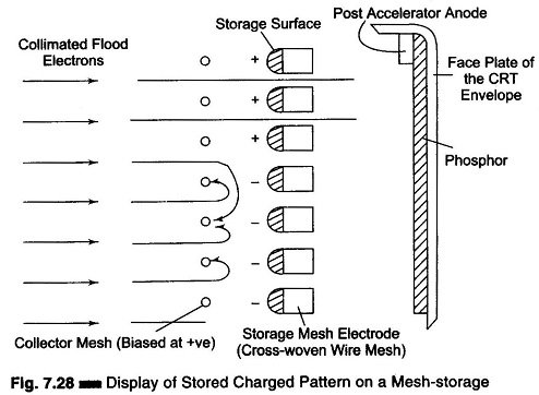
The positively charged areas allow the electrons to pass through to the post accelerator region and the display target phosphor. The negatively charged region repels the flood electrons back to the collector mesh. Thus the charge pattern on the storage surface appears reproduced on the CRT display phosphor just as though it were being traced with a deflected beam.
Figure 7.28 shows a display of the stored charge pattern on a mesh storage.