Squelch Circuit:
Squelch (muting): When no carrier is present at the input, i.e., in the absence of transmissions on a given channel or between stations, a sensitive receiver will produce a disagreeable amount of loud noise. This is because AGC disappears in the absence of any carrier. The receiver acquires its maximum sensitivity and amplifies the noise present at its input. In some circumstances this is not particularly important, but in many others it can be annoying and tiring. Systems such as those used by the police, ambulances and coast radio stations, in which a receiver must be monitored at all times but transmission is sporadic, are the principal beneficiaries of squelch. It enables the receiver’s output to remain cut off unless the carrier is present. Apart from eliminating inconvenience, such a system must naturally increase the efficiency of the operator. Squelch Circuit is also called muting or quieting. Quiescent (or quiet) AGC and Codan (carrier-operated device, antinoise) are similar systems.
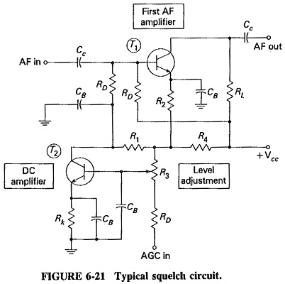
The squelch circuit, as shown in Figure 6-21, consists of a dc amplifier to which AGC is applied and which operates upon the first audio amplifier of the receiver. When the AGC voltage is low or zero, the dc amplifier, T2, draws current so that the voltage drop across its load resistor R1 cuts off the audio amplifier, T1; thus no signal or noise is passed. When the AGC voltage becomes sufficiently negative to cut off T2, this de amplifier no longer draws collector current, so that the only bias now on T1 is its self-bias, furnished by the bypassed emitter resistor R2 and also by the base potentiometer resistors. The audio amplifier now functions as though the squelch circuit were not there.
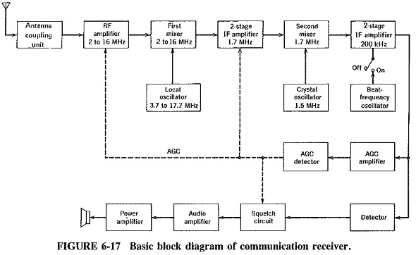
Resistor R3 is a dropping resistor, whose function it is to ensure that the dc voltage supplied to the collector and base potentiometer of T1 is higher than the dc voltage supplied (indirectly) to its emitter. Manual adjustment of R3 will allow the cut-in bias of T2 to be varied so that quieting may be applied for a selected range of AGC values. This facility must be provided, otherwise weak stations, not generating sufficient AGC, might be cut off. The squelch circuit is normally inserted immediately after the detector, as shown in Figures 6-17 and 6-21.
Tuning calibration: Tuning calibration consists of having a built-in crystal oscillator, usually nonsinusoidal, operating at 500 to 1000 kHz, whose output may be fed to the input of the receiver by throwing the appropriate switch. With the beat-frequency oscillator in operation (to follow), whistles will now be heard at 500- or 1000-kHz intervals, especially since the crystal oscillator works into a resistive load, so as not to attenuate harntonics of the fundamental frequency. The calibration of the receiver may now be corrected by adjustment of the pointer or cursor, which must be movable independently of the gang. An elaborate receiver, which is also tunable to frequencies above 30 MHz, may have a built-in crystal amplifier, whose function is to amplify the higher harmonics of the crystal oscillator to make frequency calibration easier at those frequencies. Synthesized receivers do not require this facility.
Beat–frequency oscillator: A communications receiver should be capable of receiving transmissions of Morse code, i.e., pulse-modulated RF carrier. In the diode detector of a normal receiver, there is no provision for registering the difference between the presence and the absence of a carrier. (This is not entirely true since there are two ways of registering the difference. First, noise comes up strongly when the carrier disappears; second, a signal-strength meter or tuning indicator would show the presence of a carrier, but much too slowly.) Such pulse-modulated dots, dashes and spaces would produce no output whatever from the detector.
In order to make Morse code audible, the receiver has a built-in BFO, normally at the detector, as shown on the block diagram of Figure 6-17. The BFO is not really a beat-frequency oscillator at all; it is merely a simple LC oscillator. The Hartley BFO is one of the favorites, operating at a frequency of 1 kHz or 400 Hz above or below the last intermediate frequency. When the IF is present, a whistle is heard in the loudspeaker, so that it is the combination of the receiver, detector, input signal and this extra oscillator which has now become a beat-frequency oscillator. Since signal is present only during a dot or a dash in Morse code, only these are heard. The code can be received satisfactorily, as can radiotelegraphy. To prevent interference, the BFO is switched off when non-telegraph reception is resumed.
Noise limiter: A fair proportion of communications receivers are provided with noise limiters. The name is a little misleading since it is patently not possible to do anything about random noise in an AM receiving system (it is possible to reduce random noise in FM). An AM noise limiter is really an impulse-noise limiter, a circuit for reducing the interfering noise pulses created by ignition systems, electrical storms or electrical machinery of various types. This is often done by automatically silencing the receiver for the duration of a noise pulse, this being preferable to a loud, sharp noise in the loudspeaker or headphones. In a common type of noise limiter, a diode is used in conjunction with a differentiating circuit. The limiter circuit provides a negative voltage as a result of the noise impulse or any very sharp voltage rise, and this negative voltage is applied to the detector, which is thus cut off. The detector then remains cut off for the duration of the noise pulse, a period that generally does not exceed a few hundred milliseconds. It is essential to provide a facility for switching off the noise limiter, or else it will interfere with Morse code or radiotelegraphy reception.