Split Phase Motor:
When a motor is provided with two windings, even though these are excited from the same voltage (supply being single-phase), the currents in the two windings can be made out-of-phase by adjustment of the impedance of the auxiliary winding in relation to the main winding. As a result F̅m and F̅a constitute an unbalanced field set with 90° elect. space-phase relationship. The two symmetrical components now being unequal Ff ≠ Fb (Ff > Fb is desired); the forward rotating field is made stronger than the backward rotating field resulting in the net production of starting torque. This is how a single-phase motor is made self-starting. In fact phase splitting can be so devised (particularly with capacitive splitting discussed soon after), wherein the backward field is reduced to zero at a specified speed resulting in a completely balanced operation. But such operation is possible only at one speed which can be optimally selected. Two important methods of Split phase Motor are namely,
- Resistance Split Phase Motor
- Capacitor Split Phase Motor
Resistance Split phase Motor:
The schematic diagram of the resistance split phase motor is given in Fig. 10.14(a). The motor employs an auxiliary winding with a higher R/X ratio as compared to the main winding.
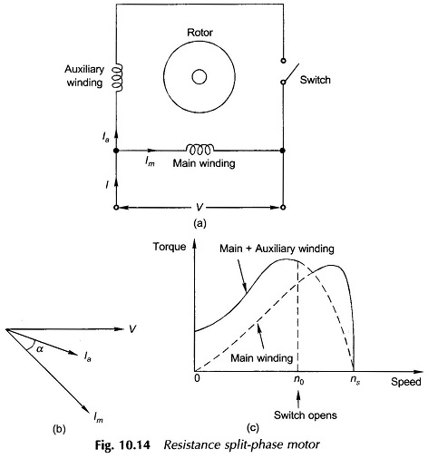
A high R/X ratio is achieved by using a smaller number of turns of thin wire for the auxiliary winding. The coil-sides of the auxiliary winding are sometimes placed on the top of the slots in order to reduce the reactance. This difference in the R/X ratio causes the auxiliary winding current Ia to lead the main winding current Im by angle α as shown in the phasor diagram of Fig. 10.14(b). The fields created by the two currents also have a phase difference of α thereby constituting an unbalanced field system. The result is the production of the starting torque as explained earlier.
The torque-speed characteristic of this motor is shown in Fig. 10.14(c) which also shows the speed n0 at which a centrifugal switch operates and thereafter the motor runs only on the main winding. The auxiliary winding need then be designed only for short-time use whereas the main winding is designed for continuous use. The value of α, the phase difference between the two currents, can at best be about 30° elect. resulting in poor starting torque as shown in Fig. 10.14(c).
Capacitor Split Phase Motor:
The problem of poor starting torque in a resistance split-phase motor is solved by using a capacitor in series with the auxiliary winding and thereby reaching the ideal case of α = 90°. The auxiliary winding along with the capacitor may be disconnected after starting. However, generally the capacitor and auxiliary windings are allowed to remain connected thereby improving the overall motor performance and in particular the power factor. Thus two types of capacitor split-phase motors (also known as capacitor motor) exist.
(a) Capacitor Start Motor:
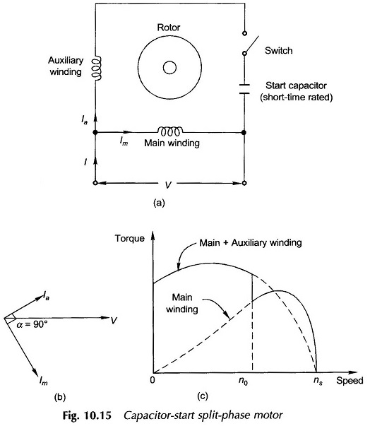
The schematic diagram of a capacitor-start motor is given in Fig. 10.15(a). The motor is so named because it uses the capacitor only for the purpose of starting. The capacitor value is usually so chosen as to give α= 90° elect. as shown in the phasor diagram of Fig. 10.15(b). The torque-speed characteristic with switching operation is shown in Fig. 10.15(c) which also shows that the starting torque is high. It may be noted that the capacitor need only be short-time rated. Because of the high VAR rating of the capacitor required, electrolytic capacitors must be employed. The range of capacitance is 250 μF or larger.
Addition of a capacitor and accompanying switch naturally increases the cost of the motor and simultaneously reduces its reliability (because of the inclusion of extra components).
(b) Two Value Capacitor Motor:
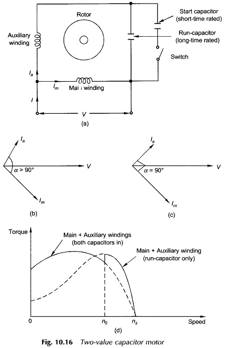
The schematic diagram of a 2-value capacitor motor is given in Fig. 10.16(a). As the name suggests, the 2-value capacitor motor not only uses a capacitor for starting but also continuous (run) operation. The capacitor used permanently is called the run-capacitor, the use of which improves the motor running performance. Figure 10.16(b) shows the phasor diagram of currents while starting (both capacitors in circuit) where α > 90° elect. so that when the start-capacitor is disconnected α becomes 90° elect. as shown in Fig. 10.16(c).
The quantitative circuit treatment could be used for design purposes to find the capacitor values for optimum performance. The practical values of α under running condition are close to 90 elect.
Figure 10.16(d) gives the torque-speed characteristics of a two-value capacitor motor. The auxiliary winding and run-capacitor can be designed to give a balanced 2-phase field set at a specified speed in which case the backward rotating field does not exist, thereby improving motor efficiency. This would also eliminate the second harmonic torques making the motor smooth running. Hence, this motor would exhibit the best start and best run characteristics with optimum efficiency at an extra cost incurred for the specially designed auxiliary winding and the capacitors.
It may be noted that the start capacitor has a large value and is rated for short-time whereas the run-capacitor required is of small value but should be rated for continuous operation entailing more expense.
It may also be noted that even if the start-capacitor is not connected at all, the motor is self-starting as the run-capacitor is still present. Though this results in reduced starting torque, the absence of the switch simplifies construction and reduces the cost. Such a motor is called the permanent-capacitor or capacitor-run motor.