Speed Control Using Slip Energy Recovery Schemes:
The foregoing discussion makes it very clear that the methods of voltage control and rotor resistance control have poor efficiency, particularly at low speeds, and find limited application. The Slip Energy Recovery Schemes is wasted in the rotor resistance, either inherent in the rotor (high resistance rotors for voltage control) or connected in the rotor circuit. The power output of the motor is rather limited. For a given power output a machine which is overdimensioned must be used.
On the other hand if the slip power can be returned to the mains, the system can be made efficient and the capacity of the drive can be increased.
With the development of thyristors static power converters can be used in the conventional and Scherbius controls to recover the slip power to the supply for speed variation. The slip variation brings in speed control.
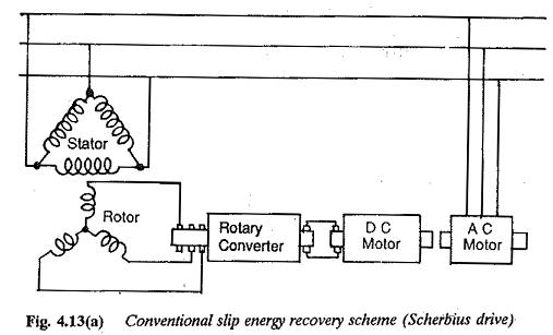
Figure 4.13 depicts a method of Slip Energy Recovery Schemes. The rotary converter and motor generator (MG) set of the conventional system are replaced by a diode rectifier and phase controlled inverter. The combination is called a converter cascade. The diode rectifier rectifies the slip power which is inverted and fed back to the mains by the inverter. The phase control of the inverter brings in speed control. In this method power flow is from the motor to the line via the dc link and therefore only speeds below synchronous speed are possible.
Slip Energy Recovery Scheme using Scherbius Drive Method:
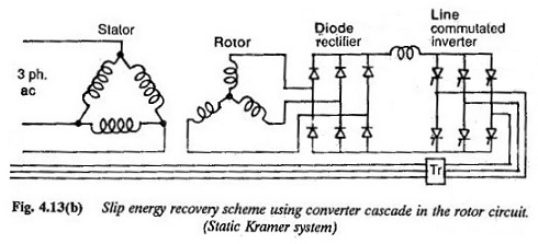
The rotor power is first rectified by a diode rectifier. This rectified voltage is fed to a line commutated inverter. The inverter applies a back emf which depends upon the firing angle. The machine operates at a speed where this balance is obtained.
Slip Energy Recovery Scheme using Static Kramer Drive System Method:
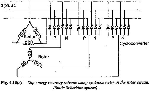
Slip Energy Recovery Scheme using Static Scherbius Drive System:
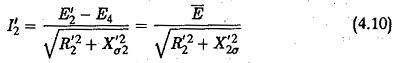
The rotor current to have a required value of current (I′2), E must be constant. If E4 varies, E′2 must also vary to keep E constant. The speed automatically varies to bring in balance. As the Slip Energy Recovery Schemes is returned to the mains the machine has fairly good efficiency. But due to the phase control of the inverter to effect the Slip Energy Recovery Schemes, the operating power factor is poor. A family of speed torque curves of Subsynchronous Converter Cascade are shown in Fig. 4.14.
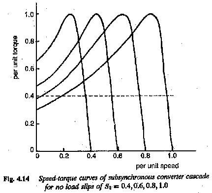
The torque developed is proportional to the dc link current. The motor has a speed-torque curve similar to that of a dc motor with separate excitation. The speed is reduced by increasing the back emf. The largest value of firing angle can only be 150° due to inverter limit of the inverter. Beyond this the firing angle cannot be increased.
The current capability of the converter cascade limits the maximum torque. The discontinuous conduction limit of the cascade decides the lowest torque. The dc link inductance connecting the diode rectifier and the inverter provides the constancy of the link current and decreases the ripple content. The ripple content is limited to 10%. The ripple content is due to the control of bridge. This causes a voltage regulation, due to which the speed of the motor is somewhat higher than the speed with continuous current.
The line power factor is poor due to the phase control of the inverter and associated reactive power for the converter. The induction motor draws a lagging current to establish the airgap flux. The power factor can be improved if the inverter can be operated near about 180° in the complete speed range. A transformer can be interposed in between the inverter and line. At the lowest speed the firing triangle is near 180° (taking the inverter limit into consideration) so that the transformer voltage matches the rotor voltage. Several methods are being developed to improve the power factor of Slip Energy Recovery Schemes employing converter cascade in the rotor.
The losses in the circuits cause a slight reduction in efficiency. This efficiency is further affected by additional losses due to the non-sinusoidal nature of the rotor current. Therefore the drive motor must be slightly overdimensioned. The motor used must have a rating 20% higher than the required power.
The lowest speed of the speed control range decides the design rating of converter. For limited speed ranges the rating can be low. Only if the speed range extends up to standstill must the cascade have full rating. When the lowest speed is other than zero, starting resistors are required to limit the starting current, as shown in Fig. 4.15. The changeover takes place from the starting resistors to the converter cascade very smoothly.
Non-sinusoidal rotor currents are responsible for torque pulsations which have a frequency six times the slip frequency. The harmonic currents are reflected to the ac line from the machine and inverter sides.
The converter cascade operates only at subsynchronous speeds due to the diode rectifier. Regeneration and speed reversal are not possible.
The design rating of the converter depends }won the speed control range required. The system is economical if this range is limited. Normally the machine cost is more. It finds application as a fan drive. Compared to the other methods of slip control this method has better efficiency but poorer power factor.
In a converter cascade the diodes and thyristors have a voltage rating decided by the lowest speed required. The rotor voltage at any slip s is given by
![]()
where V20 is the rotor voltage at standstill. If the speed range required is down to standstill the rotor voltage changes from 0 to V20.
![]()
For a three-phase bridge rectifier the dc voltage output
The back emf provided by the inverter must be equal to the dc voltage of the rectifier. The inverter voltage
![]()
where Vdi is the inverter dc voltage. Taking maximum value α = 150° taking inverter limit into consideration the maximum value of the dc voltage is
![]()
From the relations of the three-phase line commutated inverter
where VL is the line voltage of the inverter. A transformer is sometimes used to match this voltage with the supply voltage and to have the desired speed range.
The maximum torque of operation decides the current rating of the diodes and thyristors. The rotor current corresponding to rated torque is available from the machine details. Using the data the maximum current
where
r represents the rated conditions.
Taking into consideration the reactive power for commutation and the form factor of rotor current by means of a factor K(> 1) the rated current can be obtained as
The corresponding dc link current is
Vs/Vsmin considers the possible fluctuation of voltage.
The converter comprising rectifier and inverter must withstand higher voltage at low speeds and higher current at small slips (high speeds).
The reactive power of this drive is more than that of the drive with variable resistance in the rotor. The power factor of the line is affected both by the reactive power of the motor and the reactive power of the converter.
The fundamental displacement factor can be derived as
An interchangeable converter cascade can be used sometimes to handle higher voltages at low speeds and higher currents at high speeds. By this the design rating of the converter unit and the size of the reactor decrease.
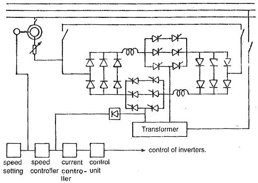
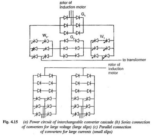
Figure 4.15 depicts one such interchangeable converter cascade in which the converter comprises two rectifiers and two inverters. Depending on the situation they are connected either in parallel or in series. At a lower speed range where the voltage to be handled is more and current is small only one rectifier G1 is connected to the rotor. The inverters W1 and W2 are connected in series via the rectifier G2. In the upper speed range (voltage is small and current is high) the converters are connected as shown in Fig. 4.15(c). There exist two parallel paths of the converters, each being one half of the total bridge. A speed range of 1 : 3 can be obtained. There is an overlap region during transition of the connection. This actually restricts the frequency of switching ON and OFF of G2 in operation around the point of interchange.