Speed Control of Induction Motor:
Stepless control of speed of induction motors cannot be carried out as efficiently and inexpensively as for dc motors. Various methods of Speed Control of Induction Motor can be visualized by consideration of the speed equation
![]()
It is seen from this equation that there are two basic methods of speed control of induction motor, namely
- Slip-Control for fixed synchronous speed, and
- Control of synchronous speed.
Since
![]()
there are two ways to control synchronous speed—control of supply frequency and control of stator poles. The latter method gives a step control as poles can be changed in multiple of two. Pole-changing is carried out in a squirrel-cage motor only and that too for two steps.
Voltage Control:
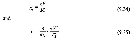
This is a slip-control method with constant frequency variable-voltage being supplied to the motor stator. Obviously the voltage should only be reduced below the rated value. For a motor operating at full-load slip, if the slip is to be doubled for constant load torque, it follows from Eqs (9.34) and (9.35) that the voltage must be reduced by a factor of 1/√2 and the corresponding current (I’2) rises to √2 of the full-load value.
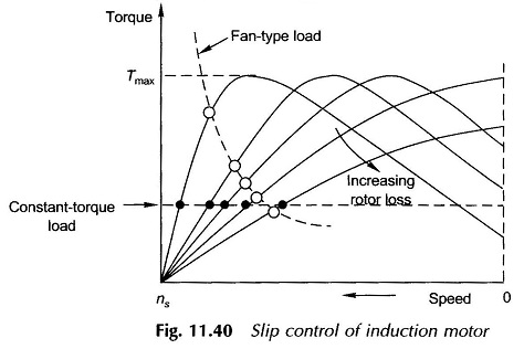
The motor, therefore, tends to get overheated. The method, therefore, is not suitable for speed control. It has a limited use for motors driving fan-type loads whose torque requirement is proportional to the square of speed(see Fig. 11.40). It is a commonly used method for ceiling fans driven by single-phase induction motors which have large standstill impedance limiting the current drawn by the stator.
Rotor-Resistance Control:
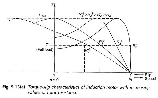
As the name indicates, this type of speed control is only possible for slip-ring induction motors. It is easily seen by referring to Fig. 9.15 that as the rotor resistance is increased, the motor slip increases (speed falls) for a fixed load torque. The stator current varies to a limited extent as the effect of changes in slip and rotor resistance tend to cancel out (refer to Eq. (9.34)) for small values of slip. The input power, however, increases. This provides for power lost in rotor additional resistance. The operating motor efficiency, of course, decreases sharply. This method of speed control as such is, therefore, adopted for a narrow speed range and usually for a short-time operation.
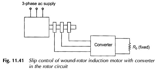
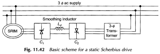
The efficiency of this type of speed-control scheme can be improved by returning the power out of the rotor mechanically to the rotor shaft or electrically to the mains. The first scheme can be implemented by a rectifier and dc motor coupled to the rotor shaft. The second scheme requires a frequency converter which converts variable-frequency power to a fixed (supply) frequency for feeding the electrical power back to the mains. These schemes can be devised by SCR circuitry ( see Figs. 11.41 and 11.42).
It is possible to achieve supersynchronous speeds by injecting power at appropriate frequency into the rotor by means of an adjustable frequency source. It may be seen that this is just the reverse of adding rotor resistance in which power is drawn out of the rotor (and wasted in external resistance). A large range of speed control both above and below synchronous is made possible by including frequency-converting equipment in the rotor circuit.
Frequency Control:
The synchronous speed of the induction motor can be controlled in a stepless way over a wide range by changing the supply frequency. As per Eq. (9.1) the resultant air-gap flux per pole is given by
![]()

Therefore, in order to avoid saturation in stator and rotor cores which would cause sharp increase in magnetization current, the flux Φr must be kept constant as f is varied. To achieve this, it follows from Eq. (9.81) that when f is varied, V must also be varied such that (V/f) remains constant. Variable (V,f) supply from constant (V,f) supply can be arranged by the converter-inverter arrangement shown schematically in Fig. 9.49(a) which employs SCR circuitry. Figure 9.49(b) shows an alternative speed-control scheme using a converter and dc motor (shunt).
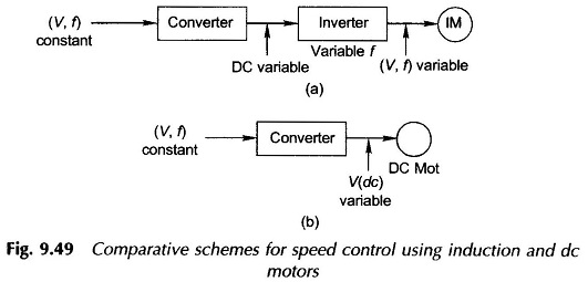
The chief attraction of employing induction motor for speed control is its ruggedness, low cost and maintenance-free operation as compared to dc motor. Because of the cost of the inverter involved in the induction motor speed-control scheme, the dc motor scheme as of today is more economical. However, the induction motor scheme is a strong candidate for speed control and is likely to take over in the near future with further improvement and cost reduction in SCR technology.