Six pulse midpoint converter:
The converter transformer converts the existing three phase system to a six phase one, since it has six secondary windings. The Six pulse midpoint converter connections are shown in Fig. 3.32.
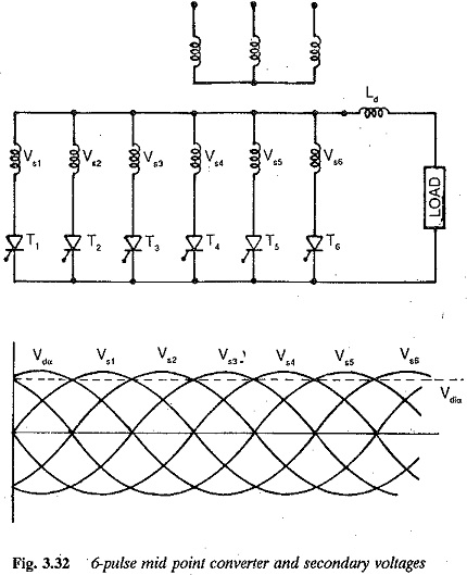
A thyristor having maximum voltage can go into conduction only if it has a firing pulse. The natural firing instant is the point of intersection of the two phase voltages in the sequence of phases. The firing angle of a thyristor is reckoned from this instant. The secondary voltages are shown in Fig. 3.32.
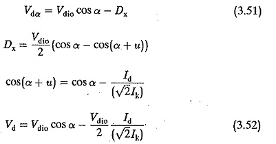
The current and voltage waveforms are shown in Fig. 3.32, assuming instantaneous commutation and ideal smoothing of dc. The average value of the dc voltage at the Six pulse midpoint converter terminals is given by
![]()
By varying the α, the output voltage can be varied steplessly. In the range of angles 0 < α < 90° the Six pulse midpoint converter operates as a rectifier. In the range of angles 90° < α < 180° it operates as an inverter. There is a limit to the firing angle (< 180°) during inversion due to the reactances, as has already been discussed.
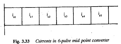
From Fig. 3.33, the effective value of the secondary current is given by
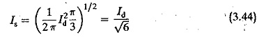
The effective value of primary current is
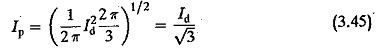
The average value of thyristor current
![]()
The rating of the secondary
![]()
and the rating of the primary
![]()
assuming a unity ratio transformer. The design rating of the transformer
![]()
The peak forward or reverse voltage of the thyristor = √2Vs.
The rms to average current ratio of the transformer is very large which is the main disadvantage of this connection. The thyristor conducts only for 60° in a period and blocks for the remaining 300°. Therefore the utilisation of the thyristor and secondary winding is somewhat poor.
The ripple content in the output voltage of the Six pulse midpoint converter can be determined as a percentage of the maximum dc voltage using Eq. 3.13 It is 4.2% at maximum voltage (α = 0°, α = 180°) and 30.8% at zero voltage (α = 90°).
The load inductance, which serves the purpose of smoothing the output voltage and decreasing the possibility of discontinuous conduction is obtained by the equation
![]()
Under ideal smoothing, the average output voltage is dropped across the resistance and the ripple content across the inductance.
The order of the harmonics present in the input current are 5, 7, 11, 13, etc. Their intensity is 20% for the 5th, 14.29%, for 7th harmonic etc. The total effective value of the rms current in the input as a percentage of the fundamental current is 104.72% and g1 = 0.955.
The performance of the converter with respect to the power factor and reactive power is similar to that of a 3-pulse converter. The fundamental displacement factor is the cosine of the firing angle and the power factor is gi cos α. The Six pulse midpoint converter gives a better performance than a 3-pulse converter.
The effects of overlap on the terminal voltage, harmonic content and inverter limit are the same as those in the case a three pulse converter.
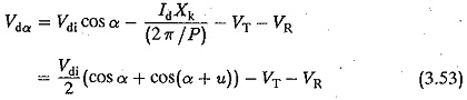
The terminal voltage of the Six pulse midpoint converter taking overlap into consideration is given by

Taking the resistance drop and device drop into consideration,
The harmonic content of the rth harmonic decreases in the ratio of (sin ru/2)/ (ru/2) due to the overlap u. The dependence of the overlap angle on the firing angle is given by
![]()
The fundamental displacement factor is approximately cos (α + u/2).
The effect of u on the reactive power consumption can be determined using Eqs 3.40-3.41.
However, because of the disadvantages of poor utilisation of thyristor, transformer secondary winding (as effective thyristor conduction is only for 60°) and the high ratio of rms to average current of the transformer and thyristors, this convertor is rarely used.