Sinusoidal PMAC Motor:
Since the voltages induced in the stator phases of a sinusoidal PMAC motor are sinusoidal, ideally, the three stator phases must be supplied with variable frequency sinusoidal voltages or currents with a phase difference of 120° between them. Behavior of such a motor from a variable frequency voltage source is already described in earlier sections. Let us now examine its behavior from a variable frequency current source.
Fig. 7.13(a) is the Norton’s equivalent of the synchronous motor equivalent circuit of Fig. 7.2. Where
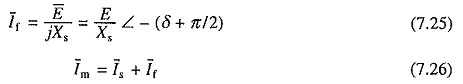
The phasor diagram of the motor with Is as a reference phasor is shown in Fig. 7.13(b). The mechanical power developed is
![]()
Substituting for E from Eq. (7.25) gives
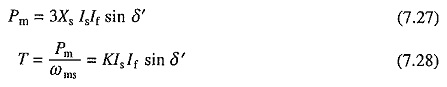
where K = 3Xs / ωms = constant.
Hence torque is proportional to Is.
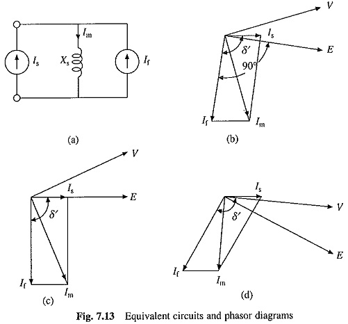
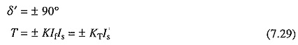
For a given value of Is, maximum torque is obtained when δ′ = π/2. Phasor diagram for δ′ = π/2 is shown in Fig. 7.13(c). In this condition, the motor is said to operate with unity internal power factor because Is is in phase with E. The motor itself has a lagging power factor. It is desirable to obtain maximum torque per unit of stator current, therefore, this is the preferred operating condition. Similarly in braking operation, maximum torque per unity of stator current is obtained when δ′ = π/2, hence this is the preferred operating condition for braking operation. The condition δ′ = π/2 is obtained by reversing stator current Is. It should be noted that δ′ is the angle between the rotating fields produced by the stator and rotor and the maximum torque is obtained when the axis of two fields make an angle of ± π/2.
Flux Weakening : There are applications which require speed control in wide range. In wound field motors, the operation up to the base speed is obtained by varying both voltage and frequency. The speed control above the base speed is obtained by reducing the air-gap flux so that motor terminal voltage remains at the rated value as frequency is increased. In Fig. 7.13(c), air-gap flux can be reduced by reducing Im. In a would field machine this can be achieved by reducing If by reducing field current. This cannot be done in a permanent magnet machine. However, Im for a given Is can be progressively reduced by increasing δ′ with speed, as shown in the phasor diagram of Fig. 7.13(d). At δ = 90°, Is is in quadrature with If For δ′ > 90°, Is can be resolved into two components, one in quadrature with If and another in phase opposition to If, which causes reduction in Im and air-gap flux.
Servo Drive Employing Sinusoidal PMAC Motor Fed from a Current Regulated Voltage Source Inverter:
The block diagram of a closed loop variable speed drive employing sinusoidal PMAC motor fed from current regulated VSI is shown in Fig. 7.14. The operation of a current regulated VSI is described in Sec. 6.18. It employs a 3-phase voltage source inverter [Fig. 6.37(a)]. The inverter is operated to supply motor three phase currents of the magnitude and phase as commanded by reference currents i*A, i*B and i*C, which are generated by a reference current generator.
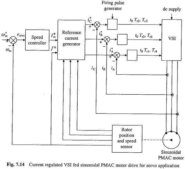
The actual speed ωm is compared with reference speed ω*m. The speed error is processed through the speed controller. The output of the speed controller sets a reference for the amplitude and polarity of the stator current I*s. The stator current templates for the three phases are generated by the rotor position sensors in such a way that δ′ = π/2. When speed error is positive the machine will work as a motor and the drive will accelerate to reference speed ω*m. If speed error is negative, braking will decelerate the motor to reference speed ω*m.
Since sinusoidal current template is to be generated based on the rotor position, an absolute rotor position sensor or resolver is required, which is expensive. Because of features like excellent dynamic performance, and low torque ripple, the drive is widely used in high performance servo drives inspite of its high cost.
For the production of maximum torque for a given stator current, the rotating fields produced by the stator and rotor should have an angle of 90°. The statorfield will be along phase A axis when the current in phase A reaches its positive peak. The rotor South Pole axis, at this instant must be 90° electrical behind. Therefore, rotor South Pole axis must be 180° electrical behind phase A axis at the positive zero crossing of phase A current. This information is utilized to locate the rotor position sensor.
A servo drive for closed-loop position control is obtained by adding a position loop around the speed loop in Fig. 7.14.