Single Sideband:
A brief, if not oversimplified, explanation of Single Sideband will help in understanding the transmission process. To begin, we must review some basic transmission processes.
- The physical length of the antenna must equal the wavelength of the transmitted signal, usually in the RF range.
- The audio signal is much too long to be transmitted directly by a conventional
- The intelligence (audio) must be processed by the electronic circuitry to meet the transmission requirements of the system. This process is known as mixing.
The Single Sideband system incorporates the mixing process plus a signal-multiplying filtering enhancement, to ensure that the signal meets the requirements of the antenna system.
If the audio (1 kHz) is mixed with a basic carrier (1 MHz), the resultant frequency will be 1.001 MHz; if the frequency is multiplied 1000 times, the resultant frequency will be 1001 MHz. If we filter out the carrier (100 MHz), a 1-MHz frequency (resultant audio) transmittable by the antenna system is left. To maintain audio quality in spite of inherent interference due to external sources, a reference carrier frequency is reinserted at the receiver and a new filtering process divides the frequency down to the audio range once again. These mixing, filtering processes take place at the lower power levels of the transmitter, allowing only the newly processed information signal to be transmitted at high power levels, thus ensuring efficiency and high fidelity.
Equation (3-7) showed that when a carrier is amplitude-modulated by a single sine wave, the resulting signal consists of three frequencies. The original carrier frequency, the upper sideband frequency (fc + fm) and the lower sideband frequency (fc – fm). This is an automatic consequence of the AM mixing process, and will always happen unless steps are taken to prevent it. Steps may be taken either during or after the modulation process, to remove or attenuate any combination of the components of the AM wave. It is the purpose of this chapter to deal with the factors involved in, and the advantages and disadvantages of, suppressing or removing the carrier and/or either of the sidebands. Generation of various forms of single-sideband modulation will also be considered.
The carrier of “standard” or double sideband, full carrier (DSBFC) AM (officially known as A3E modulation) conveys no information. This is because the carrier component remains constant in amplitude and frequency, no matter what the modulating voltage does. Just as the fact that the two sidebands are images of each other, since each is affected by changes in the modulating voltage amplitude via the exponent mVc/2. All the information can be conveyed by the use of one sideband. The carrier is superfluous, and the other sideband is redundant. The main reason for the widespread use of A3E is the relative simplicity of the modulating and demodulating equipment. Furthermore, A3E is the acceptable form used for broadcasting. The fact that radical, i.e., expensive, changes in home receivers would be required if SSB were introduced on a large scale has so far prevented any such changes, although “compatible” Single Sideband has been proposed from time to time. This form of SSB would require no changes in domestic receivers.
The AM power equation states that the ratio of total power to carrier power is given by (1 + m2/2):1. If the carrier is suppressed, only the sideband power remains. As this is only Pc(m2/2), a two-thirds saving is effected at 100 percent modulation, and even more is saved as the depth of modulation is reduced. If one of the sidebands is now also suppressed, the remaining power is Pc(m2/4), a further saving of 50 percent over carrier-suppressed AM.
In practice, Single Sideband is used to save power in applications where such a power saving is warranted, i.e., in mobile systems, in which weight and power consumption must naturally be kept low. Single-sideband modulation is also used in applications in which bandwidth is at a premium. Point-to-point communications, land, air and mari-time mobile communications, television, telemetry, military communications, radio navigation and amateur radio are the greatest users of SSB in one form or another.
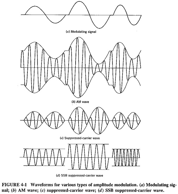
Waveforms showing Single Sideband are illustrated in Figure 4-1, together with the modulating voltage, the corresponding AM voltage, and a wave with the carrier removed. Two different modulating amplitudes and frequencies are shown for comparison. This demonstrates that here the Single Sideband wave is a single radio frequency. Its amplitude is proportional to the amplitude of the modulating voltage, and its frequency varies with the frequency of the modulating signal. An upper sideband is shown so that its frequency increases with that of the modulation, but please note that this frequency increase is exaggerated here to indicate the effect clearly.