What is Silicon Controlled Rectifier (SCR)? | Construction and Working of SCR:
What is Silicon Controlled Rectifier (SCR)? – This semiconductor switching device is also known as a thyristor. It is a 4-layer, 3-junction, bistable (ON and OFF) semiconductor switch. The terminal to the outer p-layer is the anode, the terminal to the outer n-layer is the cathode and the terminal to the inner p-layer is the gate as shown in the schematic diagram and the symbolic representation of Fig. 11.3(a).
The anode is connected to a heat sink base providing a rigid platform for the SCR. The rating of the SCR has very much improved since its introduction in 1967 and now SCRs voltage rating 10 kV and an rms current rating of 3500 A with speed of 1 μs corresponding to a power-handling capacity of 30 MW are available. A device of such a high rating can be switched on by a low voltage supply of about 1 A and 10 W which gives us an idea of the tremendous power amplification of this device (3 x 10⁶). Because of its compactness, high reliability and low loss, the SCR has almost replaced the earlier power switching devices thyratron and magnetic amplifier.
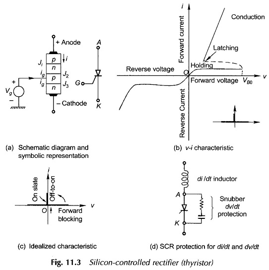
Figure 11.3(b) shows the static v-i characteristic of the Silicon Controlled Rectifier which is similar to that of the diode in the reverse direction. The forward characteristic is the same up to the turn-on (or breakdown) voltage (VB0) at which avalanche multiplication starts and the current begins to rise rapidly to a value determined by the supply voltage and the external impedance. The Silicon Controlled Rectifier latches on and this is the conducting mode (state). The SCR stays in this mode till the forward current is brought below the holding current level (a few milliamperes) and at this point it reverts to the forward blocking state (J1 and J3 forward biased and J2 reverse biased). By increasing the gate or trigger current, both the forward break-down voltage and the holding current can be reduced. Thus the SCR can be made to fire, i.e. to conduct at a specified forward voltage, by controlling the gate current. Ideal characteristic of the Silicon Controlled Rectifier is shown in Fig. 11.3(c).
Silicon Controlled Rectifier has three Operating Modes:
- Forward blocking mode (J1 and J3 forward biased and J2 reverse biased). This is the off-state.
- Forward conducting mode: the on-state.
- Reverse blocking mode (J1 and J3 reverse biased and J2 forward biased)—this is also the off-state.
When forward biased the SCR can be turned on by any of the following four ways:
- When a positive trigger pulse is applied to the gate, the Silicon Controlled Rectifier switches rapidly to the conditioning mode, after a brief delay. The total turn-on time which comprises delay and rise times is of the order of 0.2 and 0.1 μs and is dependent upon the character of the trigger pulse. The SCR continues to conduct after the trigger pulse has ceased provided the thyristor current has become more than the latching current which is slightly more than the holding current.
- The SCR can also be turned on by increasing the forward voltage beyond the forward breakdown voltage VBO.
- An SCR may turn on (without any gate pulse) if the forward voltage is applied suddenly. This is called as dv/dt turn on and it may result in improper operation of the circuit. A simple R-C snubber (see Fig 11.3(d)) is normally used to limit the dv/dt of the applied forward voltage.
- If the current in a thyristor rises at too high a rate, that is, high di/dt, the device can be destroyed. Some inductance, therefore, must be inserted in series to keep di/dt below a safe limit
The gate control method, i.e. applying a positive gate signal to the forward-biased SCR is an efficient and simple method of turning on the SCR and is commonly applied. Using gate control, the device can be triggered either by a dc gate signal or by a pulsed-gate signal. The total turn-on time depends on the anode circuit parameters, the gate signal amplitude and its rise time.
A conducting SCR can be switched off only by reducing its conduction current below the holding current (a few mA) and being reverse-biased (i.e. the cathode positive with respect to the anode) for a minimum turn-off time (10-100 μs). Also, the rate of rise of the anode voltage after turn-off must be limited, otherwise the device may start conducting again.
An important consideration in the use of SCRs in motor control is the means by which turn-off or commutation is achieved and the associated commutation circuitry—its complexity, cost and weight. In ac circuits the current goes through a natural zero value causing the device to be automatically turned off. This is known as natural or line commutation. Here the SCR has to be triggered synchronously with or without delay with the zero crossing of the voltage across it whenever it is positively biased. In dc circuit application where is no natural current zero, the forward current through the SCR can be reduced by shunting it with a low impedance path or by applying a reverse voltage across it forcing the forward current to zero value—this is known as forced commutation.
An SCR gets fired spuriously by an excessive rate of rise (dv/dt) of the anode voltage. System transient voltages of a spike waveform have to be suppressed by input filters.
The Necessary Protective Features are:
- temperature limitation to avoid thermal run-away,
- protection against overcurrent (e.g. caused by a short circuit),
- suppression of impulsive transient voltages and currents.
There are mainly two types of SCRs for use in motor controllers—inverter grade and converter grade. The inverter grade SCRs are used in inverters, cyclo-converters, and brushless dc motor systems while the converter grade are employed in choppers, phase-controlled rectifiers, ac regulators, etc. These two grades vary in their time responses. Inverter grade SCRs are costlier than the converter grade.
Since the introduction of SCRs, their power and voltage ratings and their characteristics have considerably improved. Further several variations of thyristors such gate-assisted turnoff thyristors (GATT), asymmetrical silicon-controlled rectifier (ASCR), reverse conducting thyristors (RCT) are used in certain applications.
Light-Activated Silicon-Controlled Rectifiers (LASCR) is a recent device which is turned on by direct radiation of silicon with light. LASCRs are used in high-voltage and high-current applications, e.g. HVDC and VAR compensators. The voltage rating of an LASCR could be as high as 4 kV at 1500 A, di/dt of 250 A/μs and dv/dt of 2 kV/μs.