Series Capacitance Voltmeter:
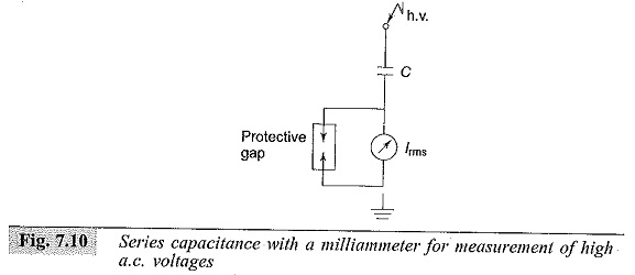
To avoid the drawbacks pointed out earlier, a Series Capacitance Voltmeter is used instead of a resistor for a.c. high voltage measurements. The schematic diagram is shown in Fig. 7.10. The current Ic through the meter is:
![]()
where,
C= capacitance of the series capacitor,
ω= angular frequency, and
V= applied a.c. voltage.
If the a.c. voltage contains harmonics, error due to changes in series impedance occurs. The rms value of the voltage V with harmonics is given by
![]()
where V1,V2,…Vn represent the rms value of the fundamental, second … and nth harmonics.
The currents due to these harmonics are
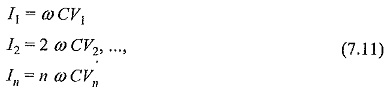
Hence, the resultant rms currents is:
![]()
With a 10% fifth harmonic only, the current is 11.2% higher, and hence the error is 11.2% in the voltage measurement.
This method is not recommended when a.c. voltages are not pure sinusoidal waves but contain considerable harmonics.
Series capacitance voltmeters were used with cascade transformers for measuring rms values up to 1000 kV. The series capacitance was formed as a parallel plate capacitor between the high voltage terminal of the transformer and a ground plate suspended above it. A rectifier ammeter was used as an indicating instrument and was directly calibrated in high voltage rms value. The meter was usually a 0-100 μA moving coil meter and the over-all error was about 2%.