Rotor Resistance Control of Induction Motor:
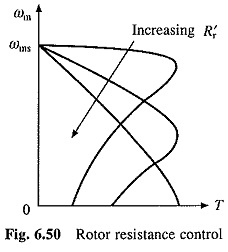
Speed-torque curves for Rotor Resistance Control of Induction Motor are given in Fig. 6.50. While maximum torque is independent of rotor resistance, speed at which the maximum torque is produced changes with rotor resistance. For the same torque, speed falls with an increase in Rotor Resistance Control of Induction Motor.
Advantage of Rotor Resistance Control of Induction Motor is that motor torque capability remains unaltered even at low speeds. Only other method which has this advantage is variable frequency control. However, cost of Rotor Resistance Control of Induction Motor is very low compared to variable frequency control. Because of low cost and high torque capability at low speeds, rotor resistance control is employed in cranes, Ward Leonard Ilgener Drives, and other intermittent load applications.
Major disadvantage is low efficiency due to additional losses in resistor connected in the rotor circuit. As the losses mainly take place in the external resistor they do not-heat the motor.
Conventional Methods:
A number of methods are used for obtaining variable resistance. In drum controllers, resistance is varied by using rotary switches and a resistance divided in few steps. Variable resistance can also be obtained by using contactors and resistors in series. High power applications use a slip-regulator, which consists of three electrodes submerged in an electrolyte, consisting of saline water. Resistance is varied by changing the distance between electrodes and earth electrode. When the power is high, electrodes are driven by a small motor. Advantage of this method is that resistance can be changed steplessly.
Static Rotor Resistance Control:
Rotor resistance can also be varied steplessly using circuit of Fig. 6.51. The ac output voltage of rotor is rectified by a diode bridge and fed to a parallel combination of a fixed resistance R and a semiconductor switch realized by a transistor Tr (Fig. 6.51).
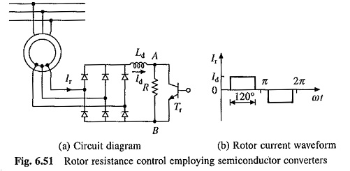
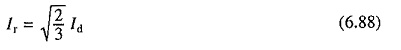
Effective value of resistance across terminals A and B, RAB, is varied by varying duty ratio of transistor Tr, which in turn varies rotor circuit resistance. Inductance Ld is added to reduce ripple and discontinuity in the dc link current Id. Rotor current waveform will be as shown. in Fig. 6.5104 when the ripple is neglected. Thus rms rotor current will be
Resistance between terminals A and B will be zero when transistor is on and it will be R when it is off. Therefore, average value of resistance between the terminals is given by
![]()
where δ is the duty ratio of the transistor and is given by Eq. (5.112).
Power consumed by RAB is
![]()
From Eqs. (6.88) and (6.89), power consumed by RAB per phase is
![]()
Equation (6.90) suggests that rotor circuit resistance per phase is increased by 0.5R(1 – δ). Thus, total rotor circuit resistance per phase will now be
![]()
RrT can be varied from Rr to (Rr + 0.5R) as δ is changed from 1 to 0.
A closed-loop speed control scheme with inner current control loop is shown in Fig. 6.52. Rotor current Ir and therefore, Id has a constant value at the maximum torque point, both during motoring and plugging. If the current limiter is made to saturate at this current, the drive will accelerate and decelerate at the maximum torque, giving very fast transient response. For plugging to occur, arrangement will have to be made for reversal of phase sequence.
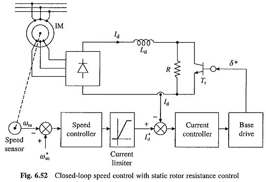
Compared to conventional Rotor Resistance Control of Induction Motor, static rotor resistance control has several advantages such as smooth and stepless control, fast response, less maintenance, compact size, simple closed-loop control and rotor resistance remains balanced between the three phases for all operating points.