Rotating Magnetic Field:
Rotating Magnetic Field – It was seen earlier that the sinusoidal current in any phase of an ac winding produces a pulsating mmf wave in space whose amplitude varies sinusoidally with time. The expression for the fundamental component of this mmf is given in Eq.(5.36).
The harmonics of the mmf wave are rendered inconsequential in a distributed winding and are still further reduced in amplitude if short-pitched coils are used. Therefore, the fundamental of the mmf wave will only be considered in the machine model given here.
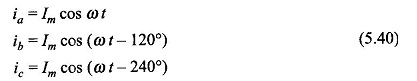
Consider now that the three phases of an ac winding are carrying balanced alternating currents
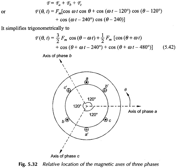
Three pulsating mmf waves are now set up in the air-gap which have a time phase difference of 120° from each other. These mmf s are oriented in space along the magnetic axes of phases a, b and c as illustrated by the concentrated coils in Fig. 5.32. Since the magnetic axes are located 120° apart in space from each other, the three mmf’s can be expressed mathematically as
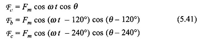
wherein it has been considered that three mmf waves differ progressively in time phase by 120°, i.e. 2π/3 rad elect. and are separated in space phase by 120°, i.e. 2π/3 rad elect. The resulting mmf wave which is the sum of the three pulsating mmf waves is
Recognizing that
![]()
it is found that the terms within the capital bracket of Eq. (5.42) represent three unit phasors with a progressive phase difference of 120° and therefore add up to zero. Hence, the resultant mmf is
![]()
It is found from Eq. (5.43) that the resultant mmf is distributed in both space and time. It indeed is a travelling wave with sinusoidal space distribution whose space phase angle changes linearly with time as 0) t. It, therefore, rotates in the air-gap at a constant speed of ω rad (elect.)/s.
The peak value of the resultant mmf is
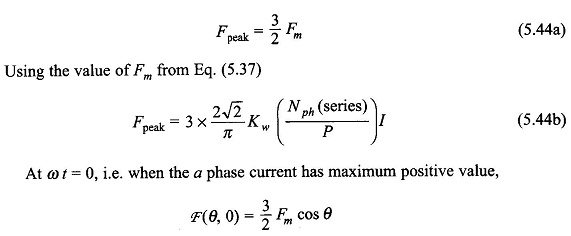
i.e. the mmf wave has its peak value (at θ = 0) lying along the axis of phase a when it carries maximum positive current. At ωt = 2π/3, the phase b (assumed lagging) has its positive current maximum, so that the peak of the travelling mmf lies along the axis of b phase. By the same argument the peak of the mmf will travel and coincide with the axis of c phase at ωt = 4π/3. It is, therefore, seen that the resultant mmf travels from the axis of the leading phase to that of the lagging phase, i.e., from phase a towards phase b and then phase c when the phase sequence of currents is abc (a leads b leads c). The direction of rotation of the resultant mmf can be reversed by simply changing the phase sequence of currents.
The speed of the Rotating Magnetic Field mmf is
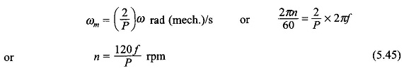
This indeed is the rotor speed to induce emf of frequency fin the ac winding. Hence this is called the synchronous speed and now onwards would be denoted by the symbol ns.
From the above discussion the following may be concluded: Whenever a balanced 3-phase winding with phases distributed in space so that the relative space angle between them is 2π/3 rad (elect.), is fed with balanced 3-phase currents relative time phase difference of 2π/3 rad (elect.), the resultant mmf rotates in the air-gap at a speed of ωs = 2πf elect. rad/s where f is the frequency of currents in Hz. The direction of rotation of the mmf is from the leading phase axis towards the lagging phase axis.
The above conclusion is easily generalized to q phases (q > 2), where the relative space-phase angle between the phase winding is 2π/q rad (elect.) and the relative time phase angle between currents is also 2π/q rad (elect). For a 2-phase winding the time and space phase angles should be π/2 rad or 90° (elect.).
Physical Picture:
Sinusoidally distributed mmf along space angle θ can be represented by a two-dimensional space vector oriented along its positive peak (towards south pole on the stator) having an amplitude equal to its peak value. For example, the mmf of a phase a in Fig. 5.33(a) is represented by the vector Fa along the positive direction of the axis of coil aa′. Sinusoidally distributed mmf s can be added by the vector method.
The mmf of phase a varies in time and space as (Eq. (5.41))
![]()
It is a pulsating wave with a fixed axis, i.e. the amplitude of the vector Fa oscillates sinusoidally with time (the exciting current is ia = Im, cos ωt with fixed axis (axis of phase a). Trigonometrically, we can write Eq. (5.46a) as

It may be seen from Eq. (5.46b) that a pulsating mmf can be considered as the sum of two (sinusoidally distributed) mmf s of same amplitude (1/2)Fm which rotates at constant speed of ω elect. rad/sec. in opposite directions; F+ of amplitude 1/2Fm rotates in the positive direction of θ and F– also of amplitude 1/2Fm rotates in the negative direction of θ. The resolution of a pulsating sinusoidally distributed mmf into two sinusoidally distributed Rotating Magnetic Field illustrated in Fig. 5.33(a).
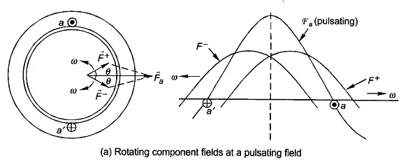
As the two component mmf’s rotate, their resultant (Fa) oscillates sinusoidally in time with its axis remaining fixed.
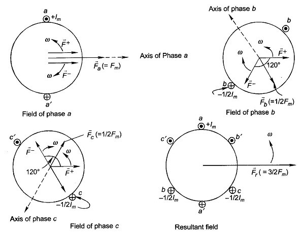
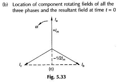
The mmf’s along the axes of coils bb’ and cc’ can be similarly resolved into two oppositely rotating mmfs of equal amplitude. Consider the instant when the phase a current is maximum positive, i.e. + Im(ia = Im cos ωt), the phase b current is at that time -1/2 Im and is becoming less negative (ib = Im cos(ωt-120°)) and the phase c current is -1/2 Im but is becoming more negative (ic = Imcos (ωt-240°)). This is also obvious from the phasor diagram of Fig. 5.33(c). Instantaneous locations of the component Rotating Magnetic Field of all the three phases are shown in Fig. 5.33(b). It is immediately observed from this figure that the three F+ are coincident and are rotating in the positive direction at speed co adding up to a positively rotating field of amplitude 3/2 Fm. The three F– are located at relative angles of 120° and are rotating in the negative direction at speed ω and thereby cancel themselves out (zero resultant field). It may be, therefore, concluded that the resultant of three pulsating mmf s of maximum amplitude Fm with 120° time phase difference having axes at relative space angles of 120° is a single Rotating Magnetic Field of strength 3/2 Fm rotating at speed ω elect. rad/s in the positive direction.
If the reluctance of the iron path of flux is neglected, the sinusoidal Rotating Magnetic Field wave creates a coincident sinusoidal rotating B-wave in the air-gap with a peak amplitude of
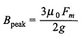
where g is the length of the machine air-gap.