Reversible Drive using Dual Converter:
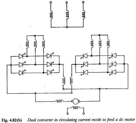
It is possible to reverse both voltage and current of the load using a dual converter. The current reversal is very fast in this case as the system is static without the mechanical output. A Reversible Drive using Dual Converter can be operated in either circulating current mode or circulating current-free mode. In the former there will not be any discontinuous conduction and control becomes very simple. About 15 to 25% of full load current is allowed as circulating current. This is limited to a chosen value by means of reactors. The change over from converter I to converter II is almost instantaneous. On the other hand, control of the converter in circulating current free mode, becomes complex. This is because change over from positive converter to negative must take place when the current is zero. The zero detection circuit should be effective during discontinuous conduction also.
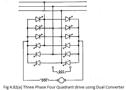
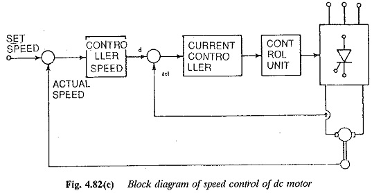
A scheme for speed reversal using a dual converter is shown in Fig. 4.82. The following stages are involved in the speed reversal. The circulating current mode is assumed.
Stage 1: The motor is under steady state in the forward direction, The converter I operates as a rectifier and converter II as inverter. The motor is unloaded.
Stage 2: This is the speed reversal stage. It is initiated with a command to reverse the speed. The firing angles are adjusted such that the converter voltage changes and the current is maintained at the limit. Converter II takes over the conduction and the power goes to the supply, as the voltage induced and Ia are in the same direction. As the kinetic energy is supplied to the line the motor retards to zero speed.
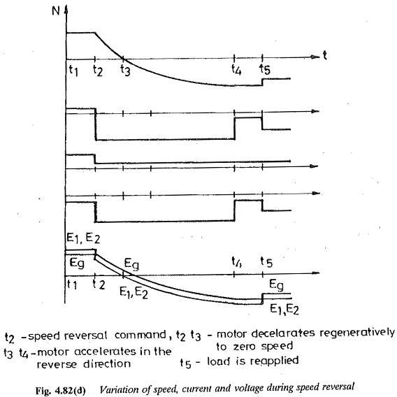
From this point onwards converter II operates as a rectifier and converter I as inverter. As the firing angle is changed the motor accelerates in the reverse direction to rated speeds.
Stage 3: The load is reapplied to the motor in the reverse direction. The waveforms of current, voltage and speed are shown in Fig. 4.82.