Reflex Klystron Oscillator:
It is possible to produce oscillations in a klystron device which has only one cavity, through which electrons pass twice. This is the Reflex Klystron Oscillator, which will now be described.
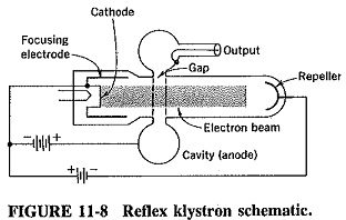
The Reflex Klystron Oscillator is a low-power, low-efficiency microwave oscillator, illustrated schematically in Figure 11-8. It has an electron gun similar to that of the multicavity klystron but smaller. Because the device is short, the beam does not require focusing. Having been formed, the beam is accelerated toward the cavity, which has a high positive voltage applied to it and, as shown, acts as the anode. The electrons overshoot the gap in this cavity and continue on to the next electrode, which they never reach.
This repeller electrode has a fairly high negative voltage applied to it, and precautions are taken to ensure that it is not bombarded by the electrons. Accordingly, electrons in the beam reach some point in the repeller space and are then turned back, eventually to be dissipated in the anode cavity. If the voltages are properly adjusted, the returning electrons given more energy to the gap than they took from it on the outward journey, and continuing oscillations take place.
Operation of Reflex Klystron:
As with the multicavity klystron, the operating mechanism is best understood by considering the behavior of individual electrons. This time, however, the reference electron is taken as one that passes the gap on its way to the repeller at the time when the gap voltage is zero and going negative. This electron is of course unaffected, overshoots the gap, and is ultimately returned to it, having penetrated some distance into the repeller space. An electron passing the gap slightly earlier would have encountered a slightly positive voltage at the gap. The resulting acceleration would have propelled this electron slightly farther into the repeller space, and the electron would thus have taken a slightly longer time than the reference electron to return to the gap. Similarly, an electron passing the gap a little after the reference electron will encounter a slightly negative voltage. The resulting retardation will,shorten its stay in the repeller space. It is seen that, around the reference electron, earlier electrons take longer to return to the gap than later electrons, and so the conditions are right for bunching to take place. The situation can be verified experimentally by throwing a series of stones upward. If the earlier stones are thrown harder, i.e., accelerated more than the later ones, it is possible for all of them to come back to earth simultaneously, i.e., in a bunch.
It is thus seen that, as in the multicavity klystron, velocity modulation is converted to current modulation in the repeller space, and one bunch is formed per cycle of oscillations. It should be mentioned that bunching is not nearly as complete in this case, and so the Reflex Klystron Oscillator is much less efficient than the multicavity klystron.
Transit Time in Reflex Klystron:
As usual with oscillators, it is assumed that oscillations are started by noise or switching transients. Accordingly, what must now be shown is that the Operation of Reflex Klystron is such as to Maintain these oscillations. For oscillations to be maintained, the transit time in the repeller space, or the time taken for the reference electron from the instant it leaves the gap to the instant of its return, must have the correct value. This is determined by investigating the best possible time for electrons to leave the gap and the best possible time for them to return.
The most suitable departure time is obviously centered on the reference electron, at the 180° point of the sine-wave voltage across the resonator gap. It is also interesting to note that, ideally, no energy at all goes into velocity-modulating the electron beam. It admittedly takes some energy to accelerate electrons, but just as much energy is gained from retarding electrons. Since just as many electrons are retarded as accelerated by the gap voltage, the total energy outlay is nil. This actually raises a most important point: energy is spent in accelerating bodies (electrons in this case), but energy is gained from retarding them. The first part of the point is obvious, and the second may be observed by means of a very simple experiment, for which the apparatus consists of a swing and a small member of the family. Once the child is swinging freely, retard the swing with some part of the body and measure the amount of energy absorbed (if still standing!).
It is thus evident that the best possible time for electrons to return to the gap is when the voltage then existing across the gap will apply maximum retardation to them. This is the time when the gap voltage is maximum positive (on the right side of the gap in Figure 11-8). Electrons then fall through the maximum negative voltage between the gap grids, thus giving the maximum amount of energy to the gap. The best time for electrons to return to the gap is at the 90° point of the sine-wave gap voltage. Returning after 1 3/4 cycles obviously satisfies these requirements, it may be stated that
![]()
where
T = transit time of electrons in repeller space, cycles
n = any integer
Modes of Reflex Klystron:
The Transit Time in Reflex Klystron obviously depends on the repeller and anode voltages, so that both must be carefully adjusted and regulated. Once the cavity has been tuned to the correct frequency, both the anode and repeller voltages are adjusted to give the correct value of T from data supplied by the manufacturer. Each combination of acceptable anode-repeller voltages will provide conditions permitting oscillations for a particular value of n. In turn, each value of it is said to correspond to a different reflex klystron mode, practical transit times corresponding to the range from 1 3/4 to 6 3/4 cycles of gap voltage. Modes corresponding to n = 2 or n = 3 are the ones used most often in practical klystron oscillators.
Practical Considerations:
Performance Reflex Klystron Oscillator with integral cavities are available for frequencies ranging from under 4 to over 200 GHz. A typical power output is 100 mW, but overall maximum powers range from 3 W in the X band to 10 mW at 220 GHz. Typical efficiencies are under 10 percent, restricting the oscillator to low-power applications.
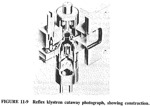
A typical X-band Reflex Klystron Oscillator is shown in Figure 11-9, approximately half life-size. The cutaway illustration reveals the internal construction of the electron gun. Part of the cavity is also visible, showing the smallness of the gap and the closeness of the repeller. The mechanical tuning arrangements are seen on the left and the waveguide output window on the right.
Tuning:
The klystron shown in Figure 11-9 has an integral cavity, but demountable cavities are also possible, as with amplifier klystrons. The frequency of resonance is mechanically adjustable by any of the methods discussed in Section 10-4.2, with the adjustable screw, bellows or dielectric insert the most popular. Such mechanical tuning of Reflex Klystron Oscillator may give a frequency variation which ranges in practice from ±20 MHz at X band to ±4 GHz at 200 GHz. Electronic tuning is also possible, by adjustment of the repeller voltage. The tuning range is about ±8 MHz at X band and ±80 MHz for submillimeter klystrons. The device is also very easy to frequency-modulate, simply by the application of the modulating voltage to the repeller.
Repeller Protection:
It is essential to make sure that the repeller of a klystron never draws current by becoming positive with respect to the cathode. Otherwise, it will very rapidly be destroyed by the impact of high-velocity electrons as well as overheating. A cathode resistor is often used to ensure that the repeller cannot be more positive than the cathode, even if the repeller voltage fails, Other precautions may include a protective diode across the klystron or an arrangement in which the repeller voltage is always applied before the cathode voltage. Manufacturers’ specifications generally list the appropriate precautions.
Application of Reflex Klystron:
The klystron oscillator has been replaced by various semiconductor oscillators in a large number of its previous applications, in new equipment. The Application of Reflex Klystron will be found in a lot of existing equipment, as a:
- Signal source in microwave generators
- Local oscillator in microwave receivers
- Frequency-modulated oscillator in portable microwave links
- Pump oscillator for parametric amplifiers
The Reflex Klystron Oscillator is still a very useful millimeter and submillimeter oscillator, producing more power at the highest frequencies than most semiconductor devices, with very low AM and FM noise.