Ratio Detector Circuit:
In the Foster-Seeley discriminator, changes in the magnitude of the input signal will give rise to amplitude changes in the resulting output voltage. This makes prior limiting necessary. It is possible to modify the discriminator circuit to provide limiting, so that the amplitude limiter may be dispensed with. A circuit so modified is called a Ratio Detector Circuit.
As we now, the sum Vao + Vbo remains constant, although the difference varies because of changes in input frequency. This assumption is not completely true. Deviation from this ideal does not result in undue distortion in the Ratio Detector Circuit, although some distortion is undoubtedly introduced. It follows that any variations in the magnitude of this sum voltage can be considered spurious here. Their suppression will lead to a discriminator which is unaffected by the amplitude of the incoming signal. It will therefore not react to noise amplitude or spurious amplitude modulation.
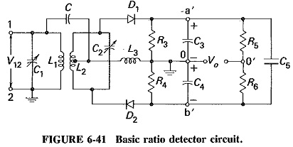
It now remains to ensure that the sum voltage is kept constant. Unfortunately, this cannot be accomplished in the phase discriminator, and the circuit must be modified. This has been done in Figure 6-41, which presents the Ratio Detector Circuit in its basic. form. This is used to show how the circuit is derived from the discriminator and to explain its operation. It is seen that three important changes have been made: one of the diodes has been reversed, a large capacitor (C5) has been placed across what used to be the output, and the output now is taken from elsewhere.
Operation:
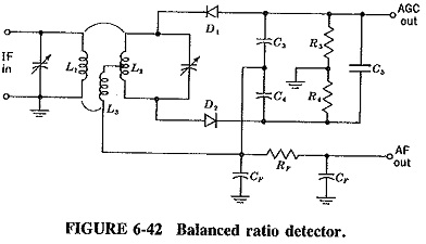
With diode D2 reversed, o is now positive with respect to b’, so that Va′b′ is now a sum voltage, rather than the difference it was in the discriminator. It is now possible to connect a large capacitor between a’ and b’ to keep this sum voltage constant. Once C5 has been connected, it is obvious that Va′b′ is no longer the output voltage; thus the output voltage is now taken between o and o′. It is now necessary to ground one of these two points, and o happens to be the more convenient, as will be seen when dealing with practical Ratio Detector Circuit. Bearing in mind that in practice R5 = R6, Vo is calculated as follows:
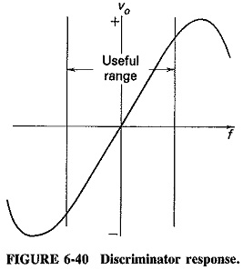
Equation (6-21) shows that the ratio detector output voltage is equal to half the difference between the output voltages from the individual diodes. Thus (as in the phase discriminator) the output voltage is proportional to the difference between the individual output voltages. The Ratio Detector Circuit therefore behaves identically to the discriminator for input frequency changes. The S curve of Figure 6-40 applies equally to both circuits.
Amplitude limiting by the ratio detector:
It is thus established that the ratio detector behaves in the same way as the phase discriminator when input frequency varies (but input voltage remains constant). The next step is to explain how the Ratio Detector Circuit reacts to amplitude changes. If the input voltage V12 is constant and has been so for some time, C5 has been able to charge up to the potential existing between a’ and b’. Since this is a dc voltage if V12 is constant, there will be no current either flowing in to charge the capacitor or flowing out to discharge it. In other words, the input impedance of C5 is infinite. The total load impedance for the two diodes is therefore the sum of R3 and R4, since these are in practice much smaller than R5 and R6.
If V12 tries to increase, C5 will tend to oppose any rise in Vo. The way in which it does this is not, however, merely to have a fairly long time constant, although this is certainly part of the operation. As soon as the input voltage tries to rise, extra diode current flows, but this excess current flows into the capacitor C5, charging it. The voltage Va′b′ remains constant at first because it is not possible for the voltage across a capacitor to change instantaneously. The situation now is that the current in the diodes load has risen, but the voltage across the load has not changed. The conclusion is that the load impedance has decreased. The secondary of the ratio detector transformer is more heavily damped, the Q falls, and so does the gain of the amplifier driving the Ratio Detector Circuit. This neatly counteracts the initial rise in input voltage.
Should the input voltage fall, the diode current will fall, but the load voltage will not, at first, because of the presence of the capacitor. The effect is that of an increased diode load impedance; the diode current has fallen, but the load voltage has remained constant. Accordingly, damping is reduced, and the gain of the driving amplifier rises, this time counteracting an initial fall in the input voltage. The ratio detector provides what is known as diode variable damping. We have here a system of varying the gain of an amplifier by changing the damping of its tuned circuit. This maintains a constant output voltage despite changes in the amplitude of the input.
Practical circuits:
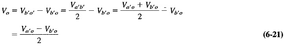
Many practical variations of the ratio detector are in use. Figure 6-41 is perhaps the best adapted to explain the principles involved and to show the similarity to the phase discriminator. It is by no means the most practical circuit. There are two types of Ratio Detector Circuit in use balanced and unbalanced. The balanced type is probably the better and more frequently employed version, and a form of it is shown in Figure 6-42.
The tertiary winding L3 serves the same purpose as did the coil L3 in the basic circuit together with the capacitor C. The primary voltage is again connected to the center tap of L2, and there is an impedance across which it is developed. This is actually an improvement on the original connection, because L3 is also used to match the low-impedance secondary to the primary, whose operation is improved if its dynamic impedance is made high. In other words, L3 gives a voltage step-down to prevent too-great damping of the primary by the ratio detector action. Such an arrangement may also be used with the phase discriminator, although the need is not so great there. This does mean that it is very easy to change a practical ratio detector circuit into a discriminator, and vice versa.
Resistors R5 and R6 of Figure 6-41 have been dispensed with. They are replaced by an arrangement in which point o of the original circuit is still a single point for RF (CF is an RF bypass capacitor connecting the C3 – C4 junction to ground for RF), but for dc it has been split into two points. The output voltage is the same as before, and it is calculated in an identical manner. The two voltage dividers are now C3 – C4 and R3 – R4, instead of R3 – R4 and R5 – R6. Two resistors have been saved.
The circuit consisting of the two capacitors CF and the resistor RF is a low-pass filter designed to remove RF ripple from the audio signal, in just the same way as the corresponding filter in the AM detector. Both diodes have been reversed in the drawing so that the top of C5 is now negative for dc. Automatic gain control may be taken for the rest of the receiver from this point.
Need for further limiting:
The time constant of the load resistors in parallel with the large capacitor is quite long. The circuit will not respond to fast amplitude changes due to noise impulses nor to the slovier changes in amplitude due to spurious amplitude modulation. Typical component values are R3 + R4 = 15 kΩ and C5 = 8μF, giving a time constant of 120 ms. A time constant much slower than this would result in a mismatch.
It is obvious, therefore, that the Ratio Detector Circuit will follow very slow amplitude changes of the input signal. The circuit will therefore not limit against changes in carrier strength due to signal strength variations caused by fading or changing from one station to another. Aircraft-produced interference, at rates of 15 Hz and less, also falls into this category. It is essential to realize that AGC is necessary in a receiver which incorporates a ratio detector. In television receivers, this AGC voltage is derived from the video detector, which is an AM detector and a more convenient source of AGC. In FM receivers AGC is obtainable from the ratio detector itself, since the voltage at the top of C5 in Figure 6-42 will vary with changes in signal strength.
Further limiting is very often also required, particularly in wideband FM broadcast receivers. This is because the Q of the Ratio Detector Circuit transformer tuned circuits is rather low. The effect is that the variable damping does not make as much difference to the gain of the driving amplifier as it would have in a narrowband system. This is especially true when the input signal increases and damping tries to reduce Q even further. A partial solution is to employ leak-type bias for the driving amplifier, in addition to a good AGC system. Alternatively, a complete stage of limiting may be used prior to the ratio detector.