Power Factor Correction Circuit:
To calculate Power Factor Correction Circuit, Consider an inductive load taking a lagging current I at a power factor cos Φ1. To develop Power Factor Improvement of this circuit, the remedy is to connect such an equipment in parallel with the load which takes a leading reactive component and partly cancels the lagging reactive component of the load. Fig. 6.6 (i) shows a capacitor connected across the load. The capacitor takes a current IC which leads the supply voltage V by 90°. The current IC partly cancels the lagging reactive component of the load current as shown in the phasor diagram in Fig. 6.6 (ii). The resultant circuit current becomes I′ and its angle of lag is Φ2. It is clear that Φ2 is less than Φ1 so that new p.f. cos Φ2 is more than the previous p.f. cos Φ1.
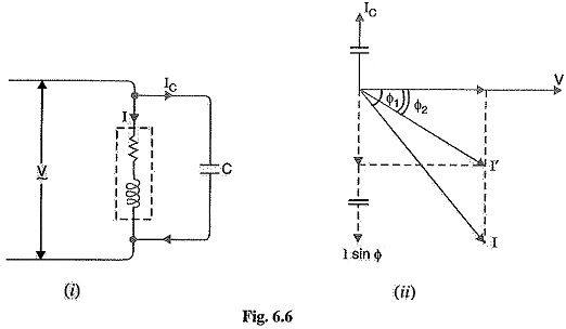
From the phasor diagram, it is clear that after Power Factor Correction Circuit, the lagging reactive component of the load is reduced to I′ sin Φ2.
Obviously,
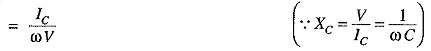
![]()
Capacitance of capacitor to improve p.f. from cos Φ1 to cos Φ2
Power triangle: The Power Factor Correction Circuit can also be illustrated referring to Fig. 6.7, the power triangle OAB is for the power factor cos cos Φ1 is for the improved power factor cos Φ2. It may be seen that active power (OA) does not change with power factor improvement. However, the lagging kVAR of the load is reduced by the Power Factor Correction Circuit equipment, thus improving the p.f. to cos Φ2.
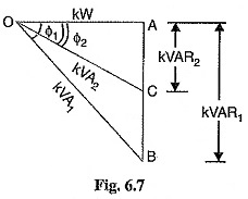
Leading kVAR supplied by p.f. correction equipment
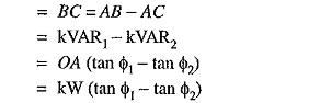
Knowing the leading kVAR supplied by the p.f. correction equipment, the desired results can be obtained.
Importance of Power Factor Improvement:
The improvement of power factor is very important for both consumers and generating stations as discussed below :
- For Consumers: A Consumers has to pay electricity charges for his maximum demand in kVA plus the units consumed. If the consumer improves the power factor, then there is a reduction in his maximum kVA demand and consequently there will be annual saving due to maximum demand charges Although power factor improvement involves extra annual expenditure on account of p.f. correction equipment, yet improvement of p.f. to a proper value results in the net annual saving for the consumer.
- For generating stations: A generating station is as much concerned with power factor improvement as the consumer. The generators in a power station are rated in kVA but the useful output depends upon kW output. As station output is kW = kVA x cos Φ, therefore, number of units supplied by it depends upon the power factor. The greater the power factor of the generating station, the higher is the kWh it delivers to the system. This leads to the conclusion that improved power factor increases the earning capacity of the power station.
Most Economical Power Factor:
If a consumer improves the power factor, there is reduction in his maximum kVA demand and hence there will be annual saving over the maximum demand charges. However, when power factor is improved, it involves capital investment on the power factor correction equipment. The consumer will incur expenditure every year in the shape of annual interest and depreciation on the investment made over the p.f. correction equipment. Therefore, the net annual saving will be equal to the annual saving in maximum demand charges minus annual expenditure incurred on p.f. correction equipment.
The value to which the power factor should be improved so as to have maximum net annual saving is known as the most economical power factor.
Meeting the Increased kW Demand on Power Stations:
The useful output of a power station is the kW output delivered by it to the supply system. Sometimes, a power station is required to deliver more kW to meet the increase in power demand. This can be achieved by either of the following two methods :
- By increasing the kVA capacity of the power station at the same power factor (say cos Φ1). Obviously, extra cost will be incurred to increase the kVA capacity of the station.
- By improving the power factor of the station from cos Φ1 to cos Φ2 without increasing the kVA capacity of the station. This will also involve extra cost on account of Power Factor Correction Circuit equipment.