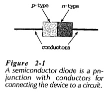
PN Junction Diode Working Principle:
A PN Junction Diode Working Principle explains about the ability to permit substantial current flow when forward-biased, and to block current when reverse-biased. Thus, it can be used as a switch; on when forward-biased, and off when biased in reverse. In PN Junction Diode Working Principle, the copper wire connecting leads becomes an electronic device known as a diode.
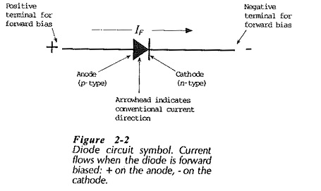
The circuit symbol (or graphic symbol) for a diode is an arrowhead and bar, (Fig. 2-2). The arrowhead indicates the conventional direction of current flow when the diode is forward biased, (from the positive terminal through the device to the negative terminal). The p-side of the diode is always the positive terminal for forward bias and is termed the anode, The n-side, called the cathode, is the negative terminal when the device is forward biased.
A PN Junction Diode Working Principle tells that it can be destroyed by a high level of forward current overheating the device. It can also be destroyed by a large reverse voltage causing the junction to breakdown. The maximum level of forward current and reverse voltage for diodes are specified on the manufacturer’s data sheets. In general physically large diodes pass the largest currents and survive the largest reverse voltages. Small diodes are limited to low current levels and low reverse voltages.
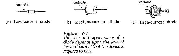
Figure 2-3 shows the appearance of low-, medium-, and high-current diodes. The body of the low-current device in Fig. 2-3(a) may be only 0.3 cm long, so the cathode is usually denoted by a coloured band. This type of diode is typically capable of passing a maximum forward current of approximately 100 mA. It can also survive about a 75 V reverse bias without breaking down, and its reverse current at 25°C is usually less than 1 μA.
The medium-current diode shown in Fig. 2-3(b) can typically pass a forward current of about 400 mA and survive over 200 V of reverse bias. The anode and cathode terminals may be indicated by a diode symbol on the side of the device.
Low-current and medium-current diodes are usually mounted by soldering the connecting leads to terminals. Power dissipated in the device is then carried away by air convection and by heat conduction along the connecting leads. High-current diodes, or power diodes [Fig. 2-3(c)], generate a lot of heat. So, air convection would be completely inadequate. Such devices are designed for mechanically connecting to a metal heat sink. Power diodes can pass forward currents of many amperes and can survive several hundred volts of reverse bias.