PLC Operation:
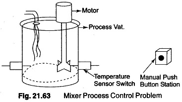
To understand the PLC Operation, consider the simple process shown in Fig. 21.63 In this process a mixer motor is to be used to automatically stir the liquid in a vat when the temperature and pressure reach a preset values. In addition, direct manual operation is also provided by means of a separate push button. The process is monitored with temperature and pressure sensor switches that close their respective contacts when conditions reach their preset values.
This control problem can be solved using the relay method for motor control shown in the relay diagram Fig. 21.64 (a)
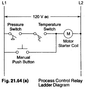
The motor starter coil (M) is energized when both the pressure and temperature switches are closed or when the manual push button is pressed.
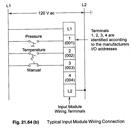
To use a PLC Operation for this process the same input field devices such as pressure switch, temperature switch and push button are used. These devices are to be hard wired to an appropriate input module according to the manufacturers labeling scheme. Typical wiring connections for a 120V AC input module are shown in Fig. 21.64(b).
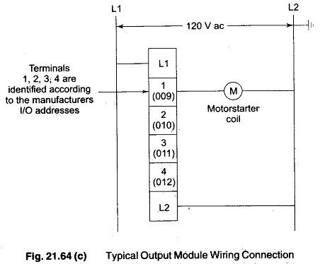
The same output field device (motor starter coil) would also be used. This device would be hard wired to an appropriate output module according to the manufacturers labeling scheme. Typical wiring connections for a 120V ac output module are shown in Fig. 21.64(c).
Next, the PLC Operation ladder logic diagram would be constructed and programmed into the memory of the CPU. A typical ladder logic diagram for this process is as shown in Fig. 21.65.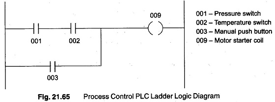
The format used is similar to the layout of the hardwired relay ladder circuit. The individual symbols represent instructions while the number represent the instruction addresses. When programming the controller these instructions are entered one by one into the processor memory from the operator terminal keyboard. Instructions are stored in the user program portion of the processor memory.
To operate the program, the PLC Operation is placed in the RUN mode, or operating cycle. During each operating cycle, the controller examines the status of input devices, executes the user program, and changes output accordingly.
Each can be thought of as a set of normally open (NO) contacts. The can be considered to represent a coil that, when energized will close a set of contacts.
In the ladder diagram shown in Fig 21.65, the coil 009 is energized when contacts 001 and 002 are closed or when 003 is closed. Either of these conditions provides a continuous path from left to right across the rung that include the coil.
The RUN operation can be described by the following sequences of events. First the inputs are examined and their status is recorded in the controllers memory (a closed contact is recorded as a signal of logic 1 and an open contact by a signal of logic 0). The ladder diagram is then executed, with each internal contact given OPEN or CLOSED status according to the record of these contacts, provide a current path from left to right in the diagram, the output coil memory location is given a logic 1 value and the output module interface contacts will close. If there is no conducting path in the program rung, the output coil memory location is set to logic ‘0’ and the output module interface contact will be open.
The completion of one cycle of this sequence by the controller is a scan. The time required for one full scan provides a measure of the speed of response of the PLC Operation and is called the scan time.