Phased Array Radars:
Phased Array Radars – Introduction With some notable exceptions, the vast majority of radars have to cover an area in searching and/or tracking, rather than always being pointed in the same direction. This implies that the antenna will have to move some limited beam movement can be produced by multiple feeds or by a moving feed antenna. As long as antenna motion is involved in moving the beam, limitations caused by inertia will always exist. A limit on the maximum scanning speed will be imposed by antenna mechanics.
The problem encountered with a single antenna of fixed shape is that the shape of the beam it produces is also constant, unless some rather complex modifications are introduced. There is the difficulty caused by the fact that a single antenna can point in only one direction at a time, therefore sending out only one beam at a time. This makes it rather difficult to track a large number of targets simultaneously and accurately. A similar difficulty is encountered when trying to track some targets while acquiring others. Such problems could be overcome, and a very significant improvement in versatility would result, if a moving beam could be produced by a stationary antenna. Although this cannot be done readily with a single antenna, it can be done with an Phased Array Radars consisting of a large number of individual radiators. Beam steering can be achieved by the introduction of variable phase differences in the individual antenna feeders, and electronic variation of the phase shifts.
Possibilities:
It was shown earlier section that a collinear dipole array can have either broadside or end-fire action. It will be recalled that the direction of the beam will be at right, angles to the plane of the Phased Array Radars if all the dipoles are fed in phase, whereas feeding them with a progressive phase difference results in a beam that is in the plane of the array, along the line joining the dipole centers. It will thus be appreciated that if the phase differences between the dipole feeds are varied between these two extremes, the direction of the beam will also change accordingly. Extending this principle one step further, it can be appreciated that a plane dipole array, with variable phase shift to the feeders, will permit moving the direction of the radiated beam in a plane rather than a line. Nor do the individual radiators have to be dipoles. Slots in waveguides and other arrangements of small omnidirectional antennas will do as well. It is possible to arrange four such antenna arrays, obtaining a full hemispherical coverage.
Each plane Phased Array Radars would, for hemispherical coverage, point 45° upward. The beam issuing from each face would have to move ±45° in elevation and ±45° in azimuth in order to cover its quadrant. In practical systems, vast numbers of individual radiators are involved. One tactical radar has, in fact, 4096 (212) radiating slots per face.
Types:
There are broadly two different types of Phased Array Radars possible. In the first, one high-power tube feeds the whole array; the array is split into a small number of subways, and a separate tube feeds each of these. The feeding is done through high-level power dividers (hybrids) and high-power phase shifters. The phase shifters are often ferrite. Indeed, most of the advances in ferrite technology in the 1960s were spin-offs from phased array military contracts. It will be recalled that the phase shift introduced by a suitable piece of ferrite depends on the magnetic field to which the ferrite is subjected. By adjusting this magnetic field, a full 360° phase change is possible.
Digital phase shifters are also available, using PIN diodes in distributed circuits. A particular section will give a phase shift that has either of two values, depending on whether the diode is ON or OFF. A typical “4-bit” digital phase shifter may consist of four PIN phase shifters in series. The first will produce a shift of either 0 or 22 1/2°, depending on the diode bias. The second offers the alternatives of 0 or 45°, the third 0 or 90° and the fourth 0 or 180°. By using various combinations, a phase shift anywhere between 0 and 360° (in 22 1/2° steps) may be provided. The ferrite phase shifters have the advantages of continuous phase shift variation and the ability to handle higher powers. PIN diode phase shifters, although they cannot handle quite such high powers, are able to provide much faster variations in phase shift and therefore beam movement. As a good guide, the phase variations that take a few milliseconds with ferrite shifters (Figure 16-17) can be accomplished in the same number of microseconds with digital shifters.
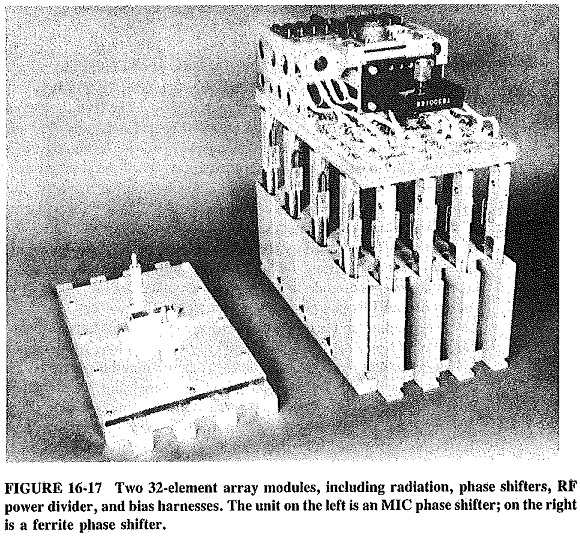
A second broad type of Phased Array Radars uses many RF generators, each of which drives a single radiating element or bank of radiating elements. Semiconductor diode generators are normally used, with phase relationships closely controlled by means of phase shifters. The use of YIG and microwave integrated circuit (MIC) phase shifters has enhanced several aspects of the phased array radar. The YIG phase shifter, when coupled with irises for matching purposes, results in a radiating element which is compact, easy to assemble and relatively inexpensive. The MIC. phase shifter greatly reduces the size of Phased Array Radars, since it is itself small and integrated into the radiating element.
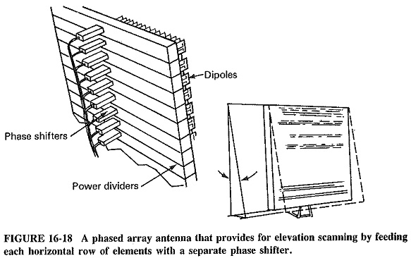
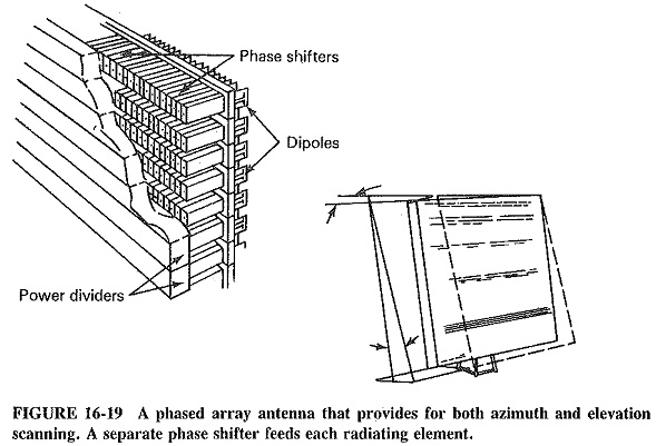
These multigenerator arrays provide wide-angle scanning over an appreciable frequency range. Scanning may be accomplished through a combination of mechanical and electronic means, or through electronic means alone. The array shown in Figure 16-18 employs RF generators to drive each horizontal bank of radiators. Elevation scanning can therefore be accomplished electronically, although horizontal scanning uses traditional mechanical techniques. The Phased Array Radars shown in Figure 16-19 provides one generator for each radiating element, and this makes electronic scanning for both horizontal and vertical planes possible, although the cost for this type of array is of course significantly higher. The number of phaser/generator elements increases from 70 for a typical array of the first type to 4900 for an array of the second type.
Arrays using multiple semiconductor diode generators have several advantages. The generators operate at much lower power levels and are therefore cheaper and more reliable. With so many independent RF generators, any failures that occur will be individual rather than total, and their effect will thus be merely a gradual deterioration, not a catastrophic failure. The disadvantages of the second system include the high cost of so many Gunn or IMPATT or even TRAPATT oscillators. The lower available powers at higher frequencies are yet another problem; even 4096 oscillators producing 100-W pulses each give out only a little over 400 kW, much less than a medium-large tube. The power dissipation is more of a problem than with tubes, since efficiencies of diode RF generators are noticeably lower.
Practicalities:
In a sense, Phased Array Radars have been the “glamour” systems, in terms of development money spent and space devoted in learned journals. Certainly, there is no doubt that they can work and currently do so in quite a number of establishments. They can be astonishingly versatile. For example, the one array can rapidly locate targets by sending out two fan-shaped beams simultaneously. One is vertical and moves horizontally, while the other is horizontal and moves vertically. Once a target has been located, it can then be tracked with a narrow beam, while other wide beams meanwhile acquire more targets. The Phased Array Radars utilizing electronic techniques benefits from inertialess scanning. Since the beam can be redirected and reconfigured in microseconds, one array can be programmed to direct pulses to various locations in rapid succession. The result is that the array can simultaneously undertake acquisition and tracking operations for multiple targets. The possibilities are almost endless.
Because Phased Array Radars have to perform complex tasks, they must them-selves also be complex. This makes them atrociously expensive. One authority quotes a typical cost of $1 million for just the phase shifters and their drivers in one system. That still leaves the computer control, RP sources, power dividers and the arrays themselves, as well as the costs of testing and installation. A significant cost reduction could be achieved by mass production, if demand for Phased Array Radars increases. It is to be hoped that this situation does not develop into a vicious circle.
Related Technology:
Signal processing is one aspect of radar technology which has resulted in a significant improvement in radar capabilities. Signal processing systems currently in use with radar systems depend heavily on computer and microchip technology. These systems perform the functions of analysing, evaluating and displaying radar data, as well as controlling the subsequent pulse emissions.
Signal processing used with radar systems includes filtering operations of the full bandwidth signal to separate signal waveforms from noise and interfering background signals. This accommodation to the electromagnetic environment in which the radar system operates is further enhanced by the ability to utilise computer algorithms to alter pulse frequency and other characteristics, in response to the transmissions of other systems. By varying the transmitted signals, it is possible for the system to attain significant immunity from interference (from other signals), Computer evaluation and control prevent interference to the system since the interfering signal cannot track the frequency changes and the subpulses generated by the system at the direction of the signal-processing computer. Usable images can be obtained even in adverse or very active electromagnetic environments. This enhancement of the radar system capability is of particular value to military and other systems which must operate in close proximity to other radars The improvement oe displays resulting from the use of computer recognition of moving targets within ground clutter. With sophisticated computer systems available to the radar, additional display manipulations and improvements can be achieved.
Radar systems benefit from large scale integration in the same way as other electronic fields, As a “signal processor on a chip” becomes a reality, the cost, complexity and size of even a complex radar system will decrease. Digital simulation of analog filters and other devices will also contribute to reduction of system costs. Because real-time radar signal processing needs to execute instructions rates exceeding 2 x 10⁷ operations per second, the current digital switching speed has become a limiting factor. As digital technology improves in speed, signal processing will become even more important for radar systems.
Planar Array Radars:
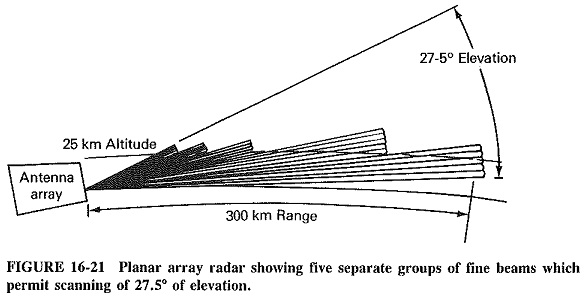
The planar array, radar uses a high-gain planar array antenna. A fixed delay is established between horizontal arrays in the elevation plane. As the frequency is changed, the phase front across the aperture tends to tilt, with the result that the beam is moved in elevation.
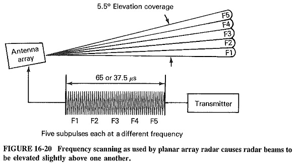
Figure 16-20 shows a planar antenna array to which a burst of five subpulses, each at a different frequency, is applied. The differing frequencies cause each successive beam to be elevated slightly more than the previous beams. A 27.5° elevation is scanned by the radar illustrated in Figure 16-21 with five of the five beam groups used. The planar array system has several advantages in that each beam group has full transmitter peak power, full antenna gain and full antenna sidelobe performance. The use of frequency changes provides economical, simple and reliable inertialess elevation scanning.