Operational Amplifier Circuit Stability:
Loop Gain and Loop Phase Shift – Consider the inverting amplifier circuit and waveforms in Fig. 15-1(a). The signal voltage voltage (vs) is amplified by a factor R2/R1, and phase shifted through -180°. The Operational Amplifier Circuit Stability is redrawn in Fig. 15-1(b) to illustrate the fact that the output voltage (vo) is divided by the feedback network to produce the feedback voltage (v).
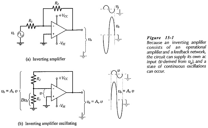
For an ac voltage (v) at the op-amp inverting input terminal [in Fig. 15-1(b)], the amplified output is vo = Avv, as shown. The output is divided by the feedback factor [B = R1/(R1 + R2)], and fed back to the input. An additional -180° of phase shift can occur within the op-amp at high frequencies, and this causes v to be in-phase with vo, as illustrated. Thus, the feed back voltage can be exactly equal to and in phase with the voltage (v) at the inverting input. In this case, the circuit is supplying its own ac input voltage, and a state of continuous oscillation exists
Because of the feedback network, high-frequency oscillations can occur in many operational amplifier circuits, and when this happens the circuit is termed unstable. Measures taken to combat Operational Amplifier Circuit Stability are referred to as frequency compensation.
Two conditions normally have to be fulfilled for a circuit to oscillate; the loop gain must be equal to or greater than 1, and the loop phase shift should equal 360°. The loop gain is the voltage gain around the loop from the inverting input terminal to the amplifier output, and back to the ‘rout via the feedback network. The loop phase shift is the total phase shift around the loop from the inverting input terminal to the amplifier output, and back to the input via the feedback network.
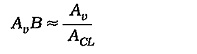
The gain from the inverting input terminal to the output is the op-amp open-loop gain (Av). For the feedback network, the gain from the amplifier output back to the input is actually an attenuation. So,
Assuming that the feedback network is purely resistive, it adds nothing to the loop phase shift. The loop phase shift is essentially the amplifier phase shift. The phase shift from the inverting input terminal to the output is normally -180°. (The output goes negative when the input goes positive, and vice versa.) At high frequencies there is additional phase shift caused by circuit capacitances, and the total can approach -360°. When this occurs, the circuit is virtually certain to oscillate. Most currently-available operational amplifiers have internal compensating components to prevent oscillations. In some cases, compensating components must be connected externally to stabilize a circuit.
Uncompensated Gain and Phase Response:
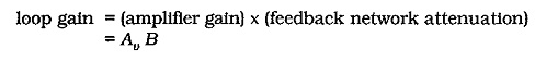
A straight-line approximation of the gain/frequency response graph for a typical operational amplifier without any compensating components is shown in Fig. 15-2. Note that the overall open-loop voltage gain (Av) initially falls off (from its 100 dB level) at 6 dB/octave (-20 dB/decade) from fp1 (pole frequency #1). From fp2, the rate of decline is 12 dB/octave (-40 dB/decade), and from fp3, the fall-off rate of Av is 18 dB/octave (-60 dB/decade).
The phase/frequency response graph in Fig. 15-2 shows that the phase shift (θ) is approximately -45° at fp1, -135° at fp2, and -225° at fp3. This open-loop phase shift is in addition to the -180° phase shift that normally occurs from the op-amp inverting input terminal to the output. Thus, the total loop phase shift ((øL) at fp1 is (-45° -180°) = -225°; at fp2, øL = (-135° -180°) = -315°; and at fp3, øL = (-225° -180°) = -405°.
As already discussed, oscillations occur when the loop gain is equals or exceeds 1 and the loop phase shift is 360°. In fact, the phase shift does not have to be exactly 360° for oscillation to occur. A phase shift of 330° at AvB = 1 makes the circuit unstable. To avoid oscillations, the total loop phase shift must not be greater than 315° when AvB = 1. The difference between 360° and the actual loop phase shift at AvB = 1 is referred to as the phase margin (øm). Thus, for Operational Amplifier Circuit Stability, the phase margin should be a minimum of,
![]()
Compensated Op-amp Gain and Phase Response:
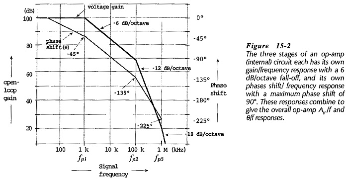
The open-loop gain/frequency and phase/frequency responses for two internally compensated operational amplifiers are shown in Figs. 15-3 and 15-4. The 741 frequency response graphs in Fig. 15-3 shows that the gain starts at 100 dB and falls by 20 dB/decade over most of its frequency range. The phase shift remains -90° or less for most of the frequency range. The open-loop gain falls off to 1 (0 dB) at a frequency of approximately 800 kHz. The 741 is known as a general purpose operational amplifier for use in relatively low frequency applications.
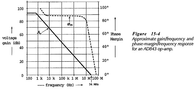
The AD843 frequency response in Fig. 15-4 shows an open-loop gain of 90 dB at low frequencies, falling off at 20 dB per decade to 34 MHz at Av =1. Instead of the open-loop phase shift, the phase margin is plotted versus frequency. The phase margin is close to 90° over much of the frequency range, starts to become smaller around 3.4 MHz, and falls to approximately 40° at f = 34 MHz.
Amplifier Stability and Gain:
The overall voltage gain of an amplifier with negative feedback is,
![]()
and the loop gain is,
So, the loop gain (AvB) equals 1 when
![]()
This is one of the conditions required for circuit oscillation. To determine if oscillation will occur in a given circuit, it is necessary to first find the frequency at which ACL ≈ Av, then determine the op-amp phase margin at that frequency.
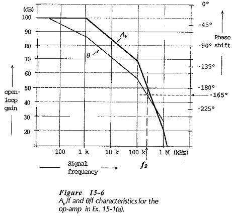
A circuit with the frequency response in Fig. 15-6 and with ACL = 50 dB was shown to be unstable. If the amplifier had ACL = 70 dB, reconsideration shows that it is stable. That is, an amplifier with a high closed-loop gain is more likely to be stable than one with the lower gain. Low gain amplifiers are more difficult to stabilize than high gain circuits. The voltage follower (with a closed-loop gain of 1) can be one of the most difficult circuits to stabilize.
Some internally compensated op-amps are specified as being stable to closed-loop gains as low as 5. In this case, external compensating components must be used with lower gain circuits.