Noise and Frequency Modulation:
Noise and Frequency Modulation is much more immune to noise than amplitude modulation and is significantly more immune than phase modulation. In order to establish the reason for this and to determine the extent of the improvement, it is necessary to examine the effect of noise on a carrier.
Effects of Noise on Carrier—Noise Triangle:
A single Noise and Frequency Modulation will affect the output of a receiver only if it falls within its bandpass. The carrier and noise voltages will mix, and if the difference is audible, it will naturally interfere with the reception of wanted signals. If such a single-noise voltage is considered vectorially, it is seen that the noise vector is superimposed on the carrier, rotating about it with a relative angular velocity ωn-ωc. This is shown in Figure 5-5. The maximum deviation in amplitude from the average value will be Vn, whereas the maximum phase deviation will be Φ = sin-1(Vn/Vc).
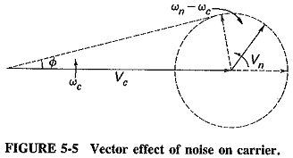
Let the noise voltage amplitude be one-quarter of the carrier voltage amplitude. Then the modulation index for this amplitude modulation by noise will be m = Vn/Vc = 0.25/1 = 0.25, and the maximum phase deviation will be Φ = sin-1 0.25/1 = 14.5°. For voice communication, an AM receiver will not be affected by the phase change. The FM receiver will not be bothered by the amplitude change, which can be removed with an amplitude limiter. It is now time to discuss whether or not the phase change affects the FM receiver more than the amplitude change affects the AM receiver.
The comparison will initially be made under conditions that will prove to be the worst case for FM. Consider that the modulating frequency (by a proper signal, this time) is 15 kHz, and, for convenience, the modulation index for both AM and FM is unity. Under such conditions the relative noise-to-signal ratio in the AM receiver will be 0.25/1 = 0.25. For FM, we first convert the unity modulation index from radians to degrees (1 rad = 57.3°) and then calculate the noise-to-signal ratio. Here the ratio is 14.5°/57.3° = 0.253, just slightly worse than in the AM case.
The effects of Noise and Frequency Modulation change must now be considered. In AM, there is no difference in the relative noise, carrier, and modulating voltage amplitudes, when both the noise difference and modulating frequencies are reduced from 15 kHz to the normal minimum audio frequency of 30 Hz (in high-quality broadcast systems). Changes in the noise and modulating frequency do not affect the signal-to-noise (S/N) ratio in AM. In FM the picture is entirely different. As the ratio of noise to carrier voltage remains constant, so does the value of the modulation index remain constant (i.e., maximum phase deviation). It should be noted that the noise voltage phase-modulates the carrier. While the modulation index due to noise remains constant (as the noise sideband frequency is reduced), the modulation index caused by the signal will go on increasing in proportion to the reduction in frequency. The signal-to-noise ratio in FM goes on reducing with frequency, until it reaches its lowest value when both signal and noise have an audio output frequency of 30 Hz. At this point the signal-to-noise ratio is 0.253 X 30/15,000 = 0.000505, a reduction from 25.3 percent at 15 kHz to 0.05 percent at 30 Hz.
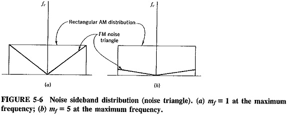
Assuming noise frequencies to be evenly spread across the frequency spectrum of the receiver, we can see that noise output from the receiver decreases uniformly with noise sideband frequency for FM. In AM it remains constant. The situation is illustrated in Figure 5-6a. The triangular noise distribution for FM is called the noise triangle. The corresponding AM distribution is of course a rectangle. It might be supposed from the figure that the average voltage improvement for FM under these conditions would be 2:1. Such a supposition might be made by considering the average audio frequency, at which FM noise appears to be relatively half the size of the AM noise. However, the picture is more complex, and in fact the FM improvement is only √3 : 1 as a voltage ratio. This is a worthwhile improvement—it represents an increase of 3:1 in the (power) signal-to-noise ratio for FM compared with AM. Such a 4.75-dB improvement is certainly worth having.
It will be noted that this discussion began with noise voltage that was definitely lower than the signal voltage. This was done on purpose. The amplitude limiter previously mentioned is a device that is actuated by the stronger signal and tends to reject the weaker signal, if two simultaneous signals are received. If peak noise voltages exceeded signal voltages, the signal would be excluded by the limiter. Under conditions of very low signal-to-noise ratio AM is the superior system. The precise value of signal-to-noise ratio at which this becomes apparent depends on the value of the FM modulation index. FM becomes superior to AM at the signal-to-noise ratio level used in the example (voltage ratio = 4, power ratio = 16 = 12 dB) at the amplitude limiter input.
A number of other considerations must now be taken into account. The first of these is that m = 1 is the maximum permissible modulation index for AM, whereas in FM there is no such limit. It is the maximum frequency deviation that is limited in FM, to 75 kHz in the wideband VHF broadcasting service. Thus, even at the highest audio frequency of 15 kHz, the modulation index in FM is permitted to be as high as 5. It may of course be much higher than that at lower audio frequencies. For example, 75 when the modulating frequency is 1 kHz. If a given ratio of signal voltage to noise voltage exists at the output of the FM amplitude limiter when m = 1, this ratio will be reduced in proportion to an increase in modulation index. When m is made equal to 2, the ratio of signal voltage to noise voltage at the limiter output in the receiver will be doubled. It will be tripled when m = 3, and so on. This ratio is thus proportional to the modulation index, and so the signal-to-noise (power) ratio in the output of an FM receiver is proportional to the square of the modulation index. When m = 5 (highest permitted when fm = 15 kHz), there will be a 25 : 1 (14-dB) improvement for FM, whereas no such improvement for AM is possible. Assuming an adequate initial signal-to-noise ratio at the receiver input, an overall improvement of 18.75 dB at the receiver output is shown at this point by wideband FM compared with AM. Figure 5-6b shows the relationship when m = 5 is used at the highest frequency.
This leads us to the second consideration, that FM has properties which permit the trading of bandwidth for signal-to-noise ratio, which cannot be done in AM. In connection with this, one fear should be allayed. Just because the deviation (and consequently the system bandwidth) is increased in an FM system, this does not necessarily mean that more random noise will be admitted. This extra random noise has no effect if the noise sideband frequencies lie outside the bandpass of the receiver. From this particular point of view, maximum deviation (and hence bandwidth) may be increased without fear.
Phase modulation also has this property and, in fact, all the noise-immunity properties of FM except the noise triangle. Since noise phase-modulates the carrier (like the signal), there will naturally be no improvement as modulating and noise sideband frequencies are lowered, so that under identical conditions FM will always be 4:75 dB better than PM for noise. This relation explains the preference for Noise and Frequency Modulation in practical transmitters.
Bandwidth and maximum deviation cannot be increased indefinitely, even for FM. When a pulse is applied to a tuned circuit, its peak amplitude is proportional to the square root of the bandwidth of the circuit. If a noise impulse is similarly applied to the tuned circuit in the IF section of an FM receiver (whose bandwidth is unduly large through the use of a very high deviation), a large noise pulse will result. When noise pulses exceed about one-half the carrier size at the amplitude limiter, the limiter fails. When noise pulses exceed carrier amplitude, the limiter goes one better and limits the signal, having been “captured” by noise. The normal maximum deviation permitted, 75 kHz, is a compromise between the two effects described.
It may be shown that under ordinary circumstances (2Vn < Vc) impulse noise is reduced in Fm to the same extent as random noise. The amplitude limiter found in AM communications receivers does not limit random noise at all, and it limits impulse noise by only about 10 dB. Noise and Frequency Modulation is better off in this regard also.
Pre-emphasis and De-emphasis:
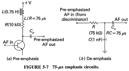
The noise triangle showed that noise has a greater effect on the higher modulating frequencies than on the lower ones. Thus, if the higher frequencies were artificially boosted at the transmitter and correspondingly cut at the receiver, an improvement in noise immunity could be expected, thereby increasing the signal-to-noise ratio. This boosting of the higher modulating frequencies, in accordance with a prearranged curve, is termed pre-emphasis, and the compensation at the receiver is called de-emphasis. An example of a circuit used for each function is shown in Figure 5-7.
Take two modulating signals having the same initial amplitude, with one of them pre-emphasized to twice this amplitude, whereas the other is unaffected (being at a much lower frequency). The receiver will naturally have to de-emphasize the first signal by a factor of 2, to ensure that both signals have the same amplitude in the output . of the receiver. Before demodulation, i.e., while susceptible to noise interference, the emphasized signal had twice the deviation it would have had without pre-emphasis and was thus more immune to noise. When this signal is de-emphasized, any noise sideband voltages are de-emphasized with it and therefore have a correspondingly lower amplitude than they would have had without emphasis. Their effect on the output is reduced.
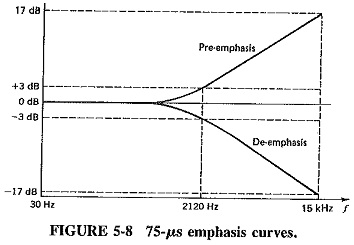
The amount of pre-emphasis in U.S. FM broadcasting, and in the sound transmissions accompanying television, has been standardised as 75 μs, whereas a number of other services, notably European and Australian broadcasting and TV sound transmission, use 50 µs. The usage of microseconds for defining emphasis is standard. A 75-μs de-emphasis corresponds to a frequency response curve that is 3 dB down at the frequency whose time constant RC is 75 μs. This frequency is given by f = 1/2 πRC and is therefore 2120 Hz. With 50-μs de-emphasis it would be 3180 Hz. Figure 5-8 shows pre-emphasis and de-emphasis curves for a 75-μs emphasis, as used in the United States.
It is a little more difficult to estimate the benefits of emphasis than it is to evaluate the other FM advantages, but subjective BBC tests with 50 μs give a figure of about 4.5 dB; American tests have shown an even higher figure with 75 μs. However,. there is a danger that must be considered; the higher modulating frequencies must not be overemphasized. The curves of Figure 5-8 show that a 15-kHz signal is pre-emphasized by about 17 dB; with 50 μs this figure would have been 12.6 dB. It must be made certain that when such boosting is applied, the resulting signal cannot over-modulate the carrier by exceeding the maximum 75-kHz deviation, since distortion will be introduced. It is seen that a limit for pre-emphasis exists, and any practical value used is always a compromise between protection for high modulating frequencies on the one hand and the risk of over modulation on the other.
If emphasis were applied to amplitude modulation, some improvement would also result, but it is not as great as in FM because the highest modulating frequencies in AM are no more affected by noise than any others. Apart from that, it would be difficult to introduce pre-emphasis and de-emphasis in existing AM services since extensive modifications would be needed, particularly in view of the huge numbers of receivers in use.
Other Forms of Interference:
In addition to noise, other forms of interference found in radio receivers include the image frequency, transmitters operating on an adjacent channel and those using the same channel. The first form will be discussed in Section 6-2.1, and the other two are discussed here.
Adjacent-channel interference: Noise and Frequency Modulation offers not only an improvement in the S/N ratio but also better discrimination against other interfering signals, no matter what their source. It was seen in the preceding section that FM having a maximum deviation of 75 kHz and 75-μs pre-emphasis gives a noise rejection at least 24 dB better than AM. Thus, if an AM receiver requires an S/N ratio of 60 dB at the detector for almost perfect reception, the FM receiver will give equal performance for a ratio no better than 36 dB. This is regardless of whether the interfering signal is due to noise or signals being admitted from an adjacent channel. The mechanism whereby the FM limiter reduces interference is precisely the same as that used to deal with random noise.
One more factor should be included in this discussion of adjacent-channel interference. When FM broadcasting systems began, AM systems had been in operation for nearly 30 years, a lot of experience with broadcasting systems had been obtained, and planners could profit from earlier mistakes. Thus, as already mentioned, each wideband FM broadcasting channel occupies 200 kHz (of which only 180 kHz is used), and the remaining 20-kHz guard band goes a long way toward reducing adjacent channel interference even further.
Cochannel interference-capture effect: The amplitude limiter works on the principle of passing the stronger signal and eliminating the weaker. This was the reason for mentioning earlier that noise reduction is obtained only when the signal is at least twice the noise peak amplitude. A relatively weak interfering signal from another transmitter will also be attenuated in this manner, as much as any other form of interference. This applies even if the other transmitter operates on the same frequency as the desired transmitter.
In mobile receivers, travelling from one transmitter toward another (cochannel) one, the interesting phenomenon of capture occurs. However, it must first be mentioned that the effect would be very straightforward with AM transmitters, The nearer transmitter would always predominate, but the other one would be heard as quite significant interference although it might be very distant.
The situation is far more interesting with FM. Until the signal from the second transmitter is less than about half of that from the first, the second transmitter is virtually inaudible, causing practically no interference. After this point, the transmitter toward which the receiver is moving becomes quite audible as a background and eventually predominates, finally excluding the first transmitter. The moving receiver has been captured by the second transmitter. If a receiver is between the two transmitters (roughly in the center zone) and fading conditions prevail, first one signal, and then the other, will be the stronger. As a result, the receiver will be captured alternatively by either transmitter. This switching from one program to the other is most distracting, of course (once the initial novelty has worn off!), and would not happen in an AM system.
Comparison of Wideband and Narrowband FM:
By convention, wideband FM has been defined as that in which the modulation index normally exceeds unity. This is the type so far discussed. Since the maximum permissible deviation is 75 kHz and modulating frequencies range from 30 Hz to 15 kHz, the maximum modulation index ranges from 5 to 2500. (The maximum permissible deviation for the sound accompanying TV transmissions is 25 kHz in the United States’ NTSC system and 50 kHz in the PAL system used in Europe and Australia. Both are wideband systems.) The modulation index in narrowband FM is near unity, since the maximum modulating frequency there is usually 3 kHz, and the maximum deviation is typically 5 kHz.
The proper bandwidth to use in an FM system depends on the application. With a large deviation, noise will be better suppressed (as will other interference), but care must be taken to ensure that impulse noise peaks do not become excessive. On the other hand, the wideband system will occupy up to 15 times the bandwidth of the narrowband system. These considerations have resulted in wideband systems being used in entertainment broadcasting, while narrowband systems are employed for communications.
Thus narrowband FM is used by the so-called FM mobile communications services. These include police, ambulances, taxicabs, radio-controlled appliance repair services, short-range VHF ship-to-shore services and the Australian “Flying Doctor” service. The higher audio frequencies are attenuated, as indeed they are in most carrier (long-distance) telephone systems, but the resulting speech quality is still perfectly adequate. Maximum deviations of 5 to 10 kHz are permitted, and the channel space is not much greater than for AM broadcasting, i.e., of the order of 15 to 30 kHz. Narrowband systems with even lower maximum deviations are envisaged. Pre-emphasis and de-emphasis are used, as indeed they are with all FM transmissions.
Stereophonic FM Multiplex System:
Stereo FM transmission is a modulation system in which sufficient information is sent to the receiver to enable it to reproduce original stereo material. It became commercially available in 1961, several years after commercial monaural transmissions. Like color TV (which of course came after monochrome TV), it suffers from the disadvantage of having been made more complicated than it needed to be, to ensure that it would be compatible with the existing system. Thus, in stereo FM, it is not possible to have a two-channel system with a left channel and a right channel transmitted simultaneously and independently, because a monaural system would not receive all the information in an acceptable form.
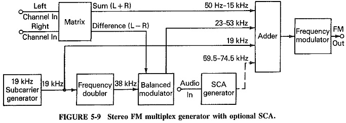
As shown in the block diagram of Figure 5-9, the two channels in the FM stereo multiplex system are passed through a matrix which produces two outputs. The sum (L + R) modulates the carrier in the same manner as the signal in a monaural transmission, and this is the signal which is demodulated and reproduced by a mono receiver tuned to a stereo transmission. The other output of the matrix is the difference signal (L – R). After demodulation in a stereo receiver, (L – R) will be added to (L + R) to produce the left channel, while the difference between the two signals will produce the right channel. This will be explained further in Chapter 6. In the meantime it is necessary to understand how the difference signal is impressed on the carrier,
What happens, in essence, is that the difference signal is shifted in frequency from the 50- to 15,000-Hz range (which it would otherwise co-occupy with the sum signal) to a higher frequency. As we know, such signal “stacking” is known as multiplexing, hence the name of the system. In this case, as in other multiplexing, a form of single sideband suppressed carrier (SSBSC) is used, with the signals to be multiplexed up being modulated onto a subcarrier at a high audio or supersonic frequency. However, there is a snag here, which makes this form of multiplexing different from the more common ones. The problem is that the lowest audio frequency is 50 Hz, much lower than the normal minimum of 300 Hz encountered in communications voice channels. This makes it difficult to suppress the unwanted sideband without affecting the wanted one; pilot carrier extraction in the receiver is equally difficult. Some form of carrier must be transmitted, to ensure that the receiver has a stable reference frequency for demodulation; otherwise, distortion of the difference signal will result.
The two problems are solved in similar ways. In the first place, the difference signal is applied to a balanced modulator (as it would be in any multiplexing system) which suppresses the carrier. Both sidebands are then used as modulating signals and duly transmitted, whereas normally one might expect one of them to be removed prior to transmission, Since the subcarrier frequency is 38 kHz, the sidebands produced by the difference signal occupy the frequency range from 23 to 53 kHz. It is seen that they do not interfere with the sum signal, which occupies the range of 50 Hz to 15 kHz.
The reason that the 38-kHz subcarrier is generated by a 19-kHz oscillator whose frequency is then doubled may now be explained. Indeed, this is the trick used to avoid the difficulty of having to extract the pilot carrier from among the close sideband frequencies in the receiver. As shown in the block diagram (Figure 5-9), the output of the 19-kHz subcarrier generator is added to the sum and difference signals in the output adder preceding the modulator. In the receiver, as we know, the frequency of the 19-kHz signal is doubled, and it can then be reinserted as the carrier for the difference signal. It should be noted that the subcarrier is inserted at a level of 10 percent, which is both adequate and not so large as to take undue power from the sum and difference signals (or to cause overmodulation). The frequency of 19 kHz fits neatly into the space between the top of the sum signal and the bottom of the difference signal. It is far enough from each of them so that no difficulty is encountered in the receiver.
The FM stereo multiplex system described here is the one used in the United States, and is in accordance with the standards established by the Federal Communications Commission (FCC) in 1961. Stereo FM has by now spread to broadcasting in most other parts of the world, where the systems in use are either identical or quite similar to the above. A Subsidiary Communications Authorisation (SCA) signal may also be transmitted in the U.S. stereo multiplex system. It is the remaining signal feeding in to the output adder. It is shown dashed in the diagram because it is not always present (See Figure 5-10). Some stations provide SCA as a second, medium-quality transmission, used as background music in stores, restaurants and other similar settings.
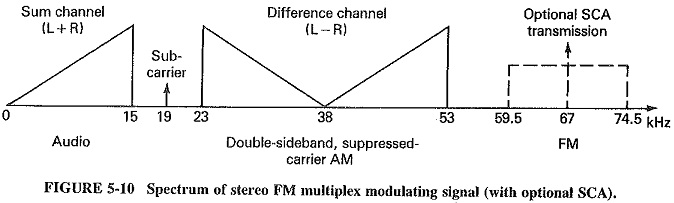
SCA uses a subcarrier at 67 kHz, modulated to a depth of ±7.5 kHz by the audio signal. Noise and Frequency Modulation is used, and any of the methods described in Section 5-3 can be employed. The frequency band thus occupied ranges from 59.5 to 74.5 kHz and fits sufficiently above the difference signal as not to interfere with it. The overall frequency allocation within the modulating signal of an FM stereo multiplex transmission with SCA is shown in Figure 5-10. The amplitude of the sum and difference signals must be reduced (generally by 10 percent) in the presence of SCA; otherwise, over modulation of the main carrier could result.