Multiplexing in Electronic Communication:
Multiplexing in Electronic Communication is the sending of a number of separate signals together, over the same cable or bearer, simultaneously and without interference. There are generally two classifications. Time Division Multiplex, or TDM, is a method of separating, in the time domain, pulses belonging to different transmissions. Use is made of the fact that pulses are generally narrow, and separation between successive pulses is rather wide. It is possible, provided that both ends of a link are synchronized, to use the wide spaces for pulses belonging to other transmissions.
On the other hand, Frequency Division Multiplex, or FDM, concerns itself with combining continuous (or analog) signals. It may be thought of as an outgrowth of independent-sideband transmission, on a much-enlarged scale; i.e., 12 or 16 channels are combined into a group, 5 groups into a supergroup, and so on, using frequencies and arrangements that are standard on a worldwide scale. Each group, supergroup or larger aggregate is then sent as a whole unit on one microwave link, cable/ or other broadband system.
Frequency Division Multiplex:
It is often necessary to send a large number of independent telephone or telegraph channels from one point to another. Between any two major cities in advanced countries, there may be requirements for thousands or even tens of thousands of simultaneous telephone, telex and data transmissions. Clearly, it would be unthinkably expensive to devote a separate cable or radio link to each transmission, and thus some kind of combination of channels (without mutual interference) is indicated. This is done in FDM by taking a bandwidth adequate for the number of channels required and allocating each channel to a frequency “slot” adjacent to the previous channel. However, for reasons of flexibility, economy and simplicity, such frequency translations are not performed in one step. Instead, standardized groupings of channels are used, and several steps of frequency translation take place before all the channels have been placed in their locations in the frequency spectrum that is transmitted in a particular link.
Group Formation:
The basic group is the smallest standard agglomeration of channels. It generally consists of 12 adjacent 4-kHz channels, occupying the frequency range from 60 to 108 kHz. A low-level pilot is transmitted at 104.08 kHz, for regulating and monitoring purposes. Narrower channels are used in many submarine cables, and so here a basic group consists of sixteen 3-kHz channels, occupying the same 48-kHz range as the 12-channel basic group. Figure 15-1 shows the channel arrangement for a basic group B in each case and also makes it apparent why the pilot in a 16-channel basic group cannot be at 104.08 kHz-84 kHz is used instead. Note that the basic group A occupies the frequency range of 12 to 60 kHz but is not normally used.
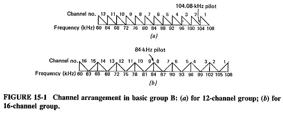
It is seen that all the channels in the basic 12-channel group B are inverted (and the group is therefore also said to be inverted). The lowest frequencies in each channel are at the upper end of the allocated frequency “slot” for that channel. As shown in Figure 15-1, the method of producing the basic group is a process of extension from single-sideband, suppressed carrier. It may be said that all 12 channels in the basic group are lower sidebands. The basic 16-channel group is a mixture of inverted and erect channels. The reasons for such arrangements are partly practical and partly historical.
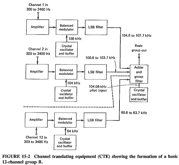
Figure 15-2 is a simplified block diagram of Channel Translating Equipment (CTE) and shows how a basic group is assembled. It is seen that the process is a repetitive one of producing adjacent lower sidebands, with a frequency separation of 900 Hz between adjoining channels. It should be noted that Figure 15-2 is a simplification, in that practical CTEs generally have four pregroup modulators, in which sub-groups of three channels are produced and then combined into a group. A 16-channel group is produced in a similar fashion, in a 16-channel CTE.
Formation of higher-order groupings:
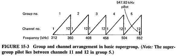
The next step up from a group is the basic supergroup, consisting of five groups, and occupying the frequency range of 312 to 552 kHz, i.e., a bandwidth of 240 kHz, as might be expected. Figure 15-3 shows the location of channels and groups in the basic supergroup. Note that the basic supergroup is erect and that, now that they have been translated higher up into the frequency spectrum, the groups are no longer called “basic.” The basic supergroup is formed in a group translating equipment (GTE), in a process similar to group formation. The super-group pilot is injected at 547.94 kHz. Supergroups may be combined to form mastergroups, supermastergroups, and so on.
It will be noted that all the descriptions so far have been related to only one direction of transmission, at least by default. What happens in a practical system, of course, is that the supergroup, etc., assembly for the reverse direction of transmission as performed in precisely the same fashion. However, supergroups belonging to opposite directions of transmission are allocated differing frequencies in the spectrum, different coaxial tubes or different optic fiber pairs, so that no confusion or interference will take place. For example, in a system where only one supergroup is required, the supergroup in one direction is allocated the frequency range from 12 to 252 kHz, and the supergroup in the other direction occupies 312 to 552 kHz, the latter corresponding to the frequency range of the basic supergroup. The next assemblage up in the hierarchy is the inastergroup (five supergroups) and then the supermastergroup (three mastergroups). The supermastergroup, or 15-supergroup assembly, is thus seen to consist of 900 channels, and about 4 MHz in each direction of transmission. All that now remains to be done is to transmit and receive the assemblage of channels.
Time Division Multiplex:
In time-division multiplex, use is made of the fact that narrow pulses with wide spaces between them are generated in any of the pulse modulation systems, so that the spaces can be used by signals from other sources. Moreover, although the spaces are relatively fixed in width, pulses may be made as narrow as desired, thus permitting the generation of high-level hierarchies.
The method of achieving TDM is best illustrated by describing the makeup of an actual system, and so a practical basic PCM system used in North America has been selected as the example. In somewhat simplified fashion, this may be described as a 24-channel system, having a sampling rate of 8000 samples per second, 8 bits (i.e.; 256 sampling levels) per sample, and a pulse width of approximately 0.625 μs. This means that the sampling interval is 1/8000 = 0.000125 s = 125 μs, and the period required for each pulse group is 8 x 0.625 = 5 μs. If there were no Multiplexing in Electronic Communication and only one channel were sent, the transmission would consist of 8000 frames per second, each made up of furious activity during the first 5 μs and nothing at all during the remaining 120 µs. This would clearly be wasteful and would represent an unnecessarily complicated method of encoding a single channel, and So this system exploits the large spaces between the pulse groups. In fact, each 125-μs frame is used to provide 24 adjacent channel time slots, with the twenty-fifth slot assigned for synchronization. Each frame consists of 193 bits-24 x 8 for each channel, plus 1 for sync, and since there are 8000 frames per second, the bit rate is 1.544 Mbit/s.
Slow-speed TDM, as often used in radio-telemetry, is produced simply with rotating mechanical switches. A number of channels are fed simultaneously to the switch in the transmitter one channel to each switch contact while the output is taken from the moving rotor. This rotates slowly and remains in contact with each channel for a predetermined period, during which time the output of that channel is the only one passed on for transmission. There is a corresponding rotating switch in the receiver, synchronized to the one in the transmitter, which reverses the process to separate the received channels.
The high-speed TDM described here uses electronic switching and delay lines to accomplish the same result. Each sampling circuit, one per channel, simultaneously receives a trigger pulse which causes it to sample its signal, and each channel output is then fed to an adder. However, whereas the output of the first sampler goes straight to the adder, that of the second is delayed by 5 μs, with a delay line or delay circuit, The output of, the third sampling circuit is similarly delayed but by 10 μs, and so on, until the twenty-fourth channel is delayed by 115 μs. In this way, each successive interval during the I25-μs frame is occupied by the transmission of a different channel, and the process is repeated 8000 times per second.
In the receiver, the output of the main detector is fed simultaneously to 24 AND gates. An AND gate, or coincidence circuit, is a simple device having one output and two or more input terminals, so arranged that an output is obtained only if all (in this case both) input signals are present. In this case each gate has two input terminals, and the second input to each gate is provided from a clock-synchronized gating generator, which is a monostable multivibrator providing rectangular pulses of 5 μs duration, 8000 times per second. Delay lines or circuits are used once again, with the gating pulse to the first gate not delayed at all, that to the second gate delayed by 5 μs and so forth. In this fashion each gate is open only during the appropriate time intervals, and the 24 channels are duly separated.
If transmission is by wire, the 1.544-Mbit/s pulse train is the signal sent, but if cable or radio communication is used, the pulse train either modulates the carrier or else is further multiplexed, with similar pulse trains, all combined together into a higher TDM hierarchical level.
Higher-order Digital Multiplexing:
The two TDM systems thus far described are generally called “primary PCM” and represent the lowest order of Multiplexing in Electronic Communication, similar to the group in FDM. As in FDM, higher orders of Multiplexing in Electronic Communication have been defined and are in use, corresponding to supergroups, mastergroups and so on. They are in use between places which have sufficient mutual traffic to warrant using such large groupings.
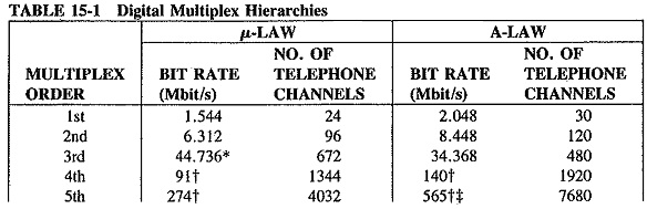
The secondary multiplex level, in both systems, is obtained from combining four primary-level signals. It provides 96 channels in the μ-law system and 120 channels in the A-law system. The bit rates are, respectively, 6.312 Mbit/s and 8.448 Mbit/s. Note that each of these rates is somewhat more than four times the corresponding primary bit rate the additional bits are necessary for synchronization and other “housekeeping” duties. The method of obtaining secondary Multiplexing in Electronic Communicationlevels consists essentially in dividing by 4 the pulse widths in the primary level signal and using the slots thus vacated to combine four primary streams, using delay lines or circuits in much the same way as was applied when the primary Multiplexing in Electronic Communication level was being produced. Still-higher TDM levels are obtained by the extension of this process, and Table 15-1 shows the levels in common use in both systems.