Moving Target Indicator Radar Block Diagram:
Basically, the Moving Target Indicator Radar Block Diagram compares a set of received echoes with those received during the previous sweep. Those echoes whose phase has remained constant are then cancelled out. This applies to echoes due to stationary objects, but those due to moving targets do show a phase change; they are thus not cancelled nor is noise, for obvious reasons. The fact that clutter due to stationary targets is removed makes it much easier to determine which targets are moving and reduces the time taken by an operator to “take in” the display. It also allows the detection of moving targets whose echoes are hundreds of times smaller than those of nearby stationary targets and which would otherwise have been completely masked. MTI can be used with a radar using a power oscillator (magnetron) output, but it is easier with one whose output tube is a power amplifier, only the latter will be considered here.
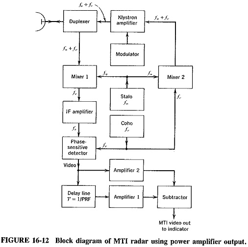
The transmitted frequency in the Moving Target Indicator Radar Block Diagram of Figure 16-12 is the sum of the outputs of two oscillators, produced in mixer 2. The first is the stab, or stable local oscillator (note that a good case can be made for using a varactor chain here). The second is the coho, or coherent oscillator, operating at the same frequency as the intermediate frequency and providing the coherent signal, which is used as will be explained. Mixers 1 and 2 are identical, and both use the same local oscillator (the stab); thus phase relations existing in their inputs are preserved in their outputs. This makes it possible to use the Doppler shift at the JF, instead of the less convenient radio frequency f0 + fc... The output of the IF amplifier and a reference signal from the coho are fed to the phase-sensitive detector, a circuit very similar to the phase discriminator.
The coho is used for the generation of the RF signal, as well as for reference in the phase detector, and the mixers do not introduce differing phase shifts. The transmitted and reference signals are locked in phase and are said to be coherent; hence the name of the coho. Since the output of this detector is phase-sensitive, an output will be obtained for all fixed or moving targets.
The phase difference between the transmitted and received signals will be constant for fixed targets, whereas it will vary for moving targets. This variation for Moving Target Indicator Radar Block Diagram is due to the Doppler frequency shift, which is naturally accompanied by a phase shift, but this shift is not constant if the target has a radial component of velocity. If the Doppler frequency is 2000 Hz and the return time for a pulse is 124 μs (10 nmi), the phase difference between the transmitted and received signals will be some value Φ, (the same as for stationary target at that point) plus 2000/124 = 16.12 complete cycles, or 16.12 X 2π = 101.4 rad. When the next pulse is returned from the moving target, the latter will now be closer, perhaps only 123 μs away, giving a phase shift of 101.4 X 123/124 = 100.7 rad. The phase shift is definitely not constant for Moving Target Indicator Radar Block Diagram. The situation is illustrated graphically, for a number of successive pulses, Figure 16-13.
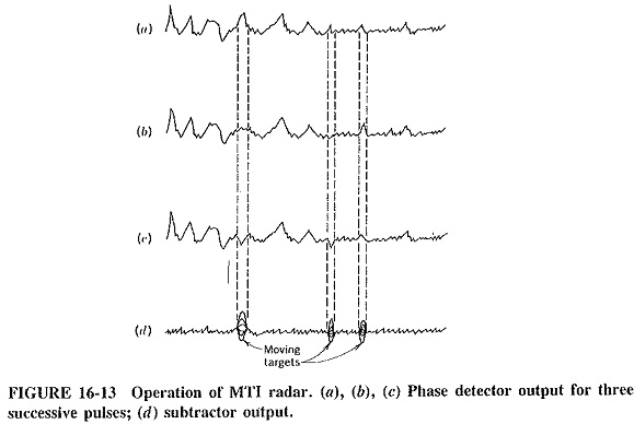
It is seen from Figure 16-13 that those returns of each pulse that correspond to stationary targets are identical with each pulse, but those portions corresponding to moving targets keep changing in phase. It is thus possible to subtract the output for each pulse from the preceding one, by delaying the earlier output by a time equal to the pulse interval, or 1/PRF. Since the delay line also attenuates heavily and since signals
must be of the same amplitude if permanent echoes are to cancel, an amplifier follows the delay line. To ensure that this does not introduce a spurious phase shift, an amplifier is placed in the undelayed line, which has exactly the same response characteristics (but a much lower gain) than amplifier 1. The delayed and undelayed signals are compared in the subtractor (adder with one input polarity reversed), whose output is shown in Figure 16-13d. This can now be rectified and displayed in the usual manner.