Microwave Link in Electronic Communication:
A Microwave Link in Electronic Communication performs the same functions as a copper or optic fiber cable, but in a different manner, by using point-to-point microwave transmission between repeaters. Many links operate in the 4- and 6-GHz region, but some links operate at frequencies as low as 2 GHz and others at frequencies as high as 13 GHz. Propagation is of course by means of the space wave and therefore limited to line of sight. Typical repeater spacings are close to 50 km, unless a city repeater is located on top of a special tower, Or a country one on a hill. Even then, much larger repeater spacings cannot be used because of the very high attenuation with distance to which radio waves are subject.
A Microwave Link in Electronic Communication terminal has a number of similarities to a coaxial cable terminal. The multiplex equipment will be very similar, if not identical, as will be the channel capacity. Where a cable system uses a number of coaxial cable pairs, a Microwave Link in Electronic Communication will use a number of carriers at various frequencies within the bandwidth allocated to the system. The effect is much the same, and once again a spare carrier is used as a “protection” bearer in case one of the working bearers fails. Finally, there are interconnections at the terminal to other microwave or cable systems, local or-trunk.
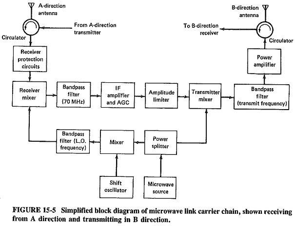
The similarities are in what is done, and the differences lie in the specific detail of how it is done. To illustrate the latter point, the simplified block diagram of a typical microwave repeater is shown in Figure 15-5. Essentially, the repeater receives a modulated microwave signal from one repeater and transmits to the next one, and an identical chain is provided for working in the other direction. The only difference here is that the transmissions in the two directions are somewhat different in frequency to avoid interference; the frequency difference is typically a few hundred megahertz at the 4- or 6-GHz operating frequencies.
The block diagram in Figure 15-5 shows no amplification of the received signal at the radio frequency. Rather, there is conversion down to an IF which is almost invariably 70 MHz, and this is the frequency at which the bulk of amplification takes place in the link shown. Indeed, low-power links have a modulated output oscillator rather than a power output amplifier, and in those links all of the amplification will take place at 70 MHz. The reason for this frequency conversion in existing links is noise reduction: until recently, it has been a lot easier to produce a very low-noise amplifier at 70 MHz than 4 GHz or above. A typical Microwave Link in Electronic Communication consists of several repeaters between the end points, and of course noise is additive for analog systems. The latest developments in microwave transistors have dramatically reduced their noise figures, and so microwave links (especially digital ones) are beginning to appear with RF preamplifiers.
One must not lose sight of the fact that having a low-noise, sensitive receiver allows the designer to reduce transmit power in proportion; if receiver noise figure can be halved, so can the required link output power. In turn, this allows cost and size reductions in every repeater of what might be a very long chain.
The antennas most frequently used are those with parabolic reflectors. Hoghorn antennas are preferred for high-density links, since they are broadband and low-noise. They also lend themselves to so-called frequency reuse, by means of separation of signals through vertical and horizontal polarization. Hoghons are widely used in the very common United States Microwave Link in Electronic Communication in the TD-2C and TD-3C series.
The circulator ensures a connection between the adjoining ports in the direction of the arrow but, not between any other ports. In Figure 15-5, this means that the transmitter is connected to the antenna and the antenna to the receiver, but the transmitter has no direct connection to the receiver input. If this were not ensured, the receiver mixer would be burned out with remarkable rapidity, The mixer is further safeguarded by protection circuits from overloads caused by any transmission, often but not always generated by transmitters connected to the same antenna.
The receiver mixer is nowadays almost exclusively a Schottky-barrier diode, since this is a very low-noise device. Indeed, other mixer diodes in older systems have generally been replaced through retrofitting with Schottky diodes. The mixer is followed by a bandpass filter, usually operating at 70 MHz and having a bandwidth in the vicinity of 12 MHz. The filter provides the selectivity of the system, ensuring that signals belonging to the other carriers in the system are rejected adequately. The IF amplifier comes next and, as mentioned, provides most of the gain of the repeater. It is almost invariably a low-noise, ultra-linear, very broadband transistor amplifier, which consists of several stages and has AGC applied to it.
The amplitude limiter follows the IF amplifier, to prevent spurious amplitude modulation. In modem links a carrier is injected at this point if the preceding link has failed and no signal is being received. If this were not done, a lot of noise would be transmitted by the link, since AGC would disappear and IF amplifier gain would rise to a maximum.
Varactor diodes are most often used in the transmitter mixer, whose function it is to bring the IF output up to the transmitting microwave frequency. This mixer is followed by a bandpass filter to prevent any straying into unauthorized portions of the frequency spectrum or interference to other carriers in the link.
The output power of a link varies, depending on the bandwidth and therefore the number of circuits per carrier, and on the distance to the next repeater. In most cases powers between 0.25 and 10 W are. transmitted, with 2 to 5 W most common. For powers of 0.5 W or less, a power amplifier is not required, and a power oscillator is used instead. This is most likely to be a reflex klystron in older equipment, a Gunn diode or an IMPATT diode in more modern equipment. The semiconductor devices are preferred for their greater reliability, lower power consumption and simpler power supply requirements. For powers of 1 to 5 W, at frequencies not exceeding 6 GHz, output amplifiers are used, being most commonly push-pull metal-ceramic disk-seal triodes or single-ended TWT amplifiers. Equipment installed during the 1980s is most likely to use FET power amplifiers. For powers in excess of about 5 W, and certainly at frequencies above 6 GHz, traveling-wave tubes are almost universal as power amplifiers. They are then preferred to semiconductor devices because of their much higher available output powers.
The microwave source was a klystron up to the 1960s, and a Gunn oscillator with AFC in the 1970s, but it is nowadays most likely to be a VHF transistor crystal oscillator, with a varactor multiplier. Multiplication factors are of the order of 20 to 40, and the power output is in the vicinity of 200 mW. The power splitter sends approximately 75 percent of the power to the transmitter mixer, and the rest to the mixer which is also fed by the shift oscillator. The function of this circuit is to ensure that the receiver mixer is fed with a frequency 70 MHz higher than the incoming signal, so as to provide the 70-MHz frequency difference for the IF amplifier. This assumes that the receive and transmit frequencies are the same and implies that the receive and transmit frequencies in the A direction in Figure 15-5 are a few hundred megahertz higher or lower than in the B direction for which the figure is drawn. Some links operate slightly differently, and their receive and transmit frequencies in a given direction are somewhat different. The shift oscillator provides the appropriately different frequency, to ensure still that an IF or 70 MHz is available. The function of the bandpass filter is to remove the unwanted frequencies from the output of the balanced mixer which precedes it.
The typical number of carriers (in each direction) in a Microwave Link in Electronic Communication is at least four, and sometimes as many as 12. There are normally 600 to 2700 channels per carrier. In difficult locations, diversity may be used, in which case it is most likely to be space diversity incorporating pairs of antennas for the same direction. Also, it must be reiterated that the repeaters are not directly involved in the modulation process. This is because they are simply repeaters; their function is to receive, amplify and retransmit. The fact that frequency changing takes place is extraneous to their function and should certainly not be confused with IF amplification in ordinary receivers (where IF amplifiers are followed by demodulators). Modulation does of course take place, as does demodulation, but only at the terminals, not at repeaters.
The towers used for Microwave Link in Electronic Communication range in height up to about 25 m, depending on the terrain, length of that particular link and location of the tower itself. Such link repeaters are unattended, and, unlike coaxial cables where direct current is fed down the cable, repeaters must have their own power supplies. The 200 to 300 W of dc power required by a link is generally provided by a battery. In turn, the power is replenished by a generator, which may be diesel, wind-driven or, in some (especially desert) locations, solar. The antennas themselves are mounted near the top of the tower, a few meters apart in the case of space diversity. They must be accurately aligned to the next repeater in the link, because beamwidths are less than 2°, and any misalignment causes a power loss. Alignment is one of the many items checked at each periodical maintenance visit to a repeater.
It was stated at the beginning of this section that microwave links and coaxial cables perform essentially the same functions. Given that, it may be thought that the two media are in competition. So they are, up to a point, but not to the extent that any one system is likely to oust the other. Basically, microwave links are cheaper and have better properties for TV transmission, although coaxial cable is much less prone to interference. (Coaxial cables are more prone to the kind of industrial interference caused by people using bulldozers and other digging appliances without first checking a map!) The preference for microwave links in transmitting TV programs to distant stations for rebroadcasting is due to the lesser number of repeaters for a given distance, as compared with a coaxial cable. In turn, this reduces the cumulative phase and amplitude distortion over the large bandwidth occupied by TV. On the other hand, a microwave link is far more subject to impulse noise, or “hits,” than the cable, which is protected’and a closed-circuit system. The overall result of these considerations is that the two media are complementary over the “backbone” routes in most developed countries, although Microwave Link in Electronic Communication predominate over the lesser routes.