Methods of Exciting Waveguides:
In order to launch a particular mode in a Methods of Exciting Waveguides, some arrangement or combination of one of more antennas is generally used. However, it is also possible to couple a coaxial line directly to a waveguide, or to couple waveguides to each other by means of slots in common walls.
Antennas:
When a short antenna, in the form of a probe or loop, is inserted into a waveguide, it will radiate, and if it has been placed correctly, the wanted mode will be set up. The correct positioning of such probes for launching common modes in rectangular waveguides is shown in Figure 10-15.
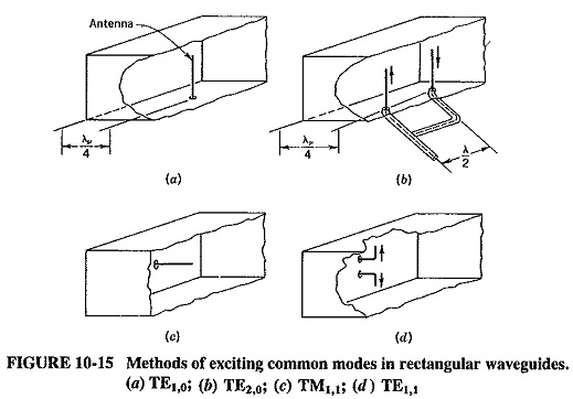
If a comparison is made with the placement of the antenna(s) corresponds to the position of the desired maximum electric field. Since each such antenna is polarized in a plane parallel to the antenna itself, it is placed so as to be parallel to the field which it is desired to set up. Needless to say, the same arrangement may be used at the other end of the waveguide to receive each such mode. When two or more antennas are employed, care must be taken to ensure that they are fed in correct phase; otherwise the desired mode will not be set up. Thus, it is seen that the two antennas used for the TE1,1 mode are in phase (in feed, not in actual orientation). However, the two antennas used to excite the TE2,0 mode are feed 180∘ , out of phase, as required by the field pattern of Figure 10-12b. Phase differences between antennas are normally achieved by means of additional pieces of transmission line, as shown here. Higher Tm,0 modes would be radiated by an extension of the principle shown. The antenna placement for the TE3,0 mode, requiring one antenna in the center of the guide, would almost certainly radiate some TE1,0 mode also. Again, the antenna used to radiate the TM1,1 mode is at right angles to the antennas used to radiate the TE modes, because of the different orientation of the electric field. Finally, note that the depth of insertion of such a probe will determine the power it couples and the impedance it encounters. Hence adjustment of this depth may be used for impedance matching as an alternative to a stub on the coaxial line.
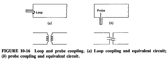
The TM0,1 mode may be launched in a circular waveguide, as shown in Figure 10-15c in the Methods of Exciting Waveguides, or else by means of a loop antenna located in a plane perpendicular to the plane of, e probe, so as to have its area intersected by a maximum number of magnetic field lines. It is thus seen that probes couple primarily to an electric field and loops to a magnetic field, but in each case both an electric and a magnetic field will be set up because the two are inseparable. Figure 10-16 shows equivalent circuits of probe and loop coupling and reinforces the idea of both fields being present regardless of which one is being primarily coupled to.
Slop Coupling:
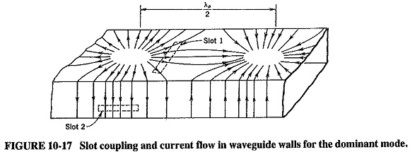
It can be appreciated that current must flow in the walls of a waveguide in which electromagnetic waves propagate. The pattern of such current flow is shown in Figure 10-17 in the Methods of Exciting Waveguides for the dominant mode. Comparison with Figures 10-11 and 10-12a shows that the current originates at points of maximum electric field intensity in the waveguide and flows in the walls because potential differences exist between various points along the walls. Such currents accompany all modes, but they have not been shown previously, to simplify the field pattern diagrams.
If a hole or slot is made in a waveguide wall, energy will escape from the waveguide through the slot or possibly enter into the waveguide from outside. As a result, coupling by means of one or more slots seems a satisfactory method of feeding energy into a waveguide from another waveguide or cavity resonator (or, alternatively, of taking energy out).
When coupling does take place, it is either because electric field lines that would have been terminated by a wall now enter the second waveguide or because the placement of a slot interrupts the flow of wall current, and therefore a magnetic field is set up extending into the second guide. Sometimes, depending on the orientation of the slot, both effects take place. In Figure 10-17 slot 1 is situated in the center of the top wall, and good deal of electric coupling takes place. On the other hand, a fair amount of wall current is interrupted, so that there will also be considerable magnetic coupling. The position of slot 2 is at a point of zero electric field, but it interrupts sizable wall current flow; thus coupling here is primarily through the magnetic field. Slots may be situated at other points in the waveguide walls, and in each case coupling will take place. It will be determined in type and amount by the position and orientation of each slot, and also by the thickness of the walls
Slot coupling is very often used between adjoining waveguides, as in directional couplers or between waveguides and cavity resonators. Because radiation will take place from a slot, such slots may be used as antennas, and in fact they very often are.
Direct Coupling to Coaxial Lines:
When a particular microwave transmission system consists of partly coaxial and partly waveguide sections, there are two standard methods of interconnection, as shown in Figure 10-18 in the Methods of Exciting Waveguides.
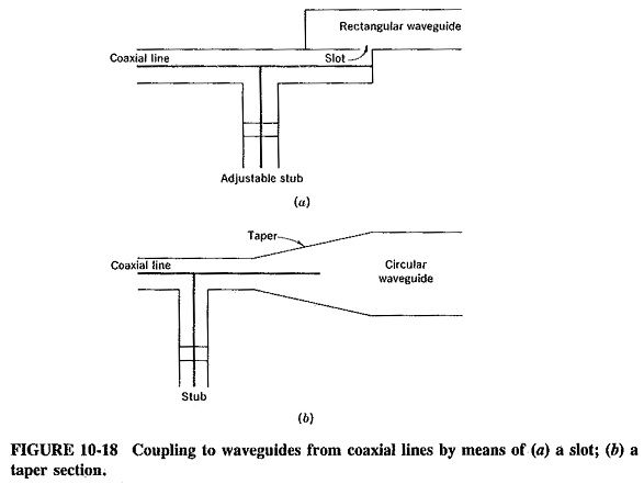
Diagram a shows a slot in a common wall, whereby energy from the coaxial line is coupled into the waveguide. In diagram b, coupling is by means of a taper section, in which the TEM mode in the coaxial line is transformed into the dominant mode in the waveguide. In each instance an impedance mismatch is likely to exist, and hence stub matching on the line is used as shown.