Measurement of Power Transmission Lines:
When power is applied to Measurement of Power Transmission Lines, the source to load impedance must be matched in its characteristics impedance (Z0). The impedance all along the line is equal to the characteristic impedance. Therefore, the transmission line is said to be correctly terminated. Hence no reflection or standing wave is produced, but only an incident or travelling wave is obtained.
The voltage distribution along the line is uniform (constant). With a loss-free line, the characteristics impedance is purely resistive and can be indicated by Ro. The power obtained in such a non-resonant transmission line equals to 12Ro or E2/R0, where I is the current flowing along the line and E is the voltage across the characteristic impedance Ro.
Power measurements done in this way, will be accurate, provided the load impedance of the transmission line closely approximates the characteristics impedance. The instrument used to measure voltages or current should not produce an appreciable reflected wave.
Thermocouple connected in series with the transmission line, can be used, to measure the current flowing in a transmission line, up to the highest frequency in the RF range. The accuracy obtainable is quite high provided the heater wire is small enough to have negligible skin effect.
The voltage across a transmission line may be determined satisfactorily by means of a diode VTVM, provided the frequency is low. The input capacitance of the voltmeter (or the voltmeter multiplier) that is shunted across the transmission line at this low frequency has a reactance that is much higher than the characteristic impedance Z0. The requirement is not satisfied when the frequency is high. The voltmeter then introduces a large reflected wave at this high frequency.
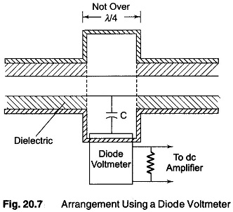
An arrangement employing a diode voltmeter is as shown in Fig. 20.7. When the voltmeter is connected to the line, an additional capacitance is added by the diode and L/C ratio is changed, the distributed L of the meter section is increased by making the diameter larger. Hence, the characteristic impedance of the meter section equals Ro and the power flow is undisturbed by the introduction of the meter.