Energy in Magnetic System:
Energy in Magnetic System – The chief advantage of electric energy over other forms of energy is the relative ease and high efficiency with which it can be transmitted over long distances. Its main use is in the form of a transmitting link for transporting other forms of energy, e.g. mechanical, sound, light, etc. from one physical location to another. Electric energy is seldom available naturally and is rarely directly utilized. Obviously two kinds of energy conversion devices are needed to convert one form of energy to the electric form and to convert it back to the original or any other desired form. Our interests in this chapter are the devices for electromechanical energy conversion. These devices can be transducers for low-energy conversion processing and transporting. These devices can be transducers for processing and transporting low-energy signals.
A second category of such devices is meant for production of force or torque with limited mechanical motion like electromagnets, relays, actuators, etc. A third category is the continuous energy conversion devices like motors or generators which are used for bulk energy conversion and utilization.
Electromechanical energy conversion takes place via the medium of a magnetic or electric field the magnetic field being most suited for practical conversion devices. Because of the inertia associated with mechanically moving members, the fields must necessarily be slowly varying, i.e. quasistatic in nature. The conversion process is basically a reversible one though practical devices may be designed and constructed to particularly suit one mode of conversion or the other.
Energy can be stored or retrieved from a magnetic system by means of an exciting coil connected to an electric source. Consider, for example the magnetic system of an attracted armature relay of Fig. 4.1.
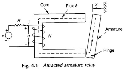
The resistance of the coil is shown by a series lumping outside the coil which then is regarded as an ideal loss-less coil. The coil current causes magnetic flux to be established in the magnetic circuit. It is assumed that all the flux Φ is confined to the iron core and therefore links all the N turns creating the coil flux linkages of
![]()
The flux linkage causes a reaction emf of
![]()
to appear at the coil terminals with polarity (as per Lenz’s law) shown in the Fig. 4.1.
The associated circuit equation is
The electric energy input into the ideal coil due to the flow of current i in time dt is
![]()
Assuming for the time being that the armature is held fixed at position x, all the input energy is stored in the magnetic field. Thus
![]()
where dWf is the change in field energy in time dt. When the expression for e in Eq. (4.2) is substituted in Eq. (4.5), we have

The relationship i-λ or ζ-λ is a functional one corresponding to the magnetic circuit which in general is nonlinear (and is also history-dependent, i.e. it exhibits hysteresis). The energy absorbed by the field for finite change in flux linkages for flux is obtained from Eq. (4.6) as
![]()
As the flux in the magnetic circuit undergoes a cycle Φ1→Φ2→Φ1, an irrecoverable loss in energy takes place due to hysteresis and eddy-currents in the iron, assuming here that these losses are separated out and are supplied directly by the electric source. This assumption renders the ideal coil and the magnetic circuit as a conservative system with energy interchange between themselves so that the net energy is conserved.
The energy absorbed by the magnetic system to establish flux Φ (or flux linkages λ from initial zero flux is 
This then is the energy of the magnetic field with given mechanical configuration when its state corresponds to flux Φ (or flux linkages λ).
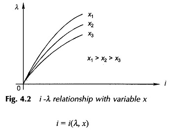
The i-λ relationship is indeed the magnetization curve which varies with the configuration variable x (Fig. 4.1: the air-gap between the armature and core varies with position x of the armature. The total reluctance of the magnetic path decreases as x increases). The i-λ relationship for various values of x is indicated in Fig. 4.2. It immediately follows that this relationship can be expressed as
According to Eqs (4.9a) and (4.9b) field energy is determined by the instantaneous values of the system states ((λ, x) or (i, x)) and is independent of the path followed by these states to reach the present values. This means that the field energy at any instant is history independent.
A change in λ, with fixed x causes electric-magnetic energy interchange governed by the circuit equation (4.3) and the energy equation (4.6). Similarly, if x is allowed to change with fixed λ, energy will interchange between the magnetic circuit and the mechanical system.
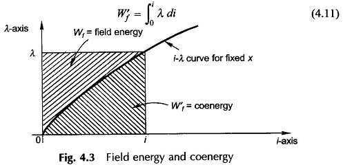
As per Eq. (4.8) the field energy is the area between the λ-axis and i-λ curve as shown in Fig. 4.3. A new term, co-energy is now defined as
![]()
wherein by expressing λ as λ(i, x), the independent variables of W′f become i and x. The coenergy on Fig. 4.3 is shown to be the complementary area of the i-λ, rectangle. It easily follows from Fig. 4.3 that
Linear Case:
Electromechanical energy conversion devices are built with air-gaps in the magnetic circuit which serve to separate the stationary and moving members. As a result the i-λ relationship of the magnetic circuit is almost linear; also the losses of magnetic origin are separately accounted for by semiempirical methods. With the linearity assumption the analysis is greatly simplified. Losses and certain nonlinear effects may then be incorporated at a later-stage.
Assuming linearity, it follows from Eq. (4.8) or Fig. 4.3 that
![]()
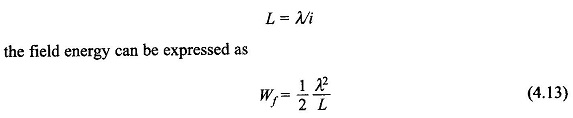
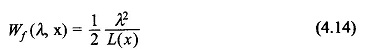
In the linear case the inductance L is independent of i but is a function of configuration x. Thus the field energy is a special function of two independent variables λ and x, i.e.
The field energy is distributed throughout the space occupied by the field. Assuming no losses and constant permeability, the energy density of the field is
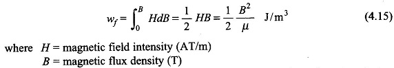
The energy density expression of Eq. (4.15) is important from the point of view of design wherein the capability of the material is to be fully utilized in arriving at the gross dimensions of the device.
For the linear case it easily follows from Eq. (4.11) that coenergy is numerically equal to energy, i.e.